|
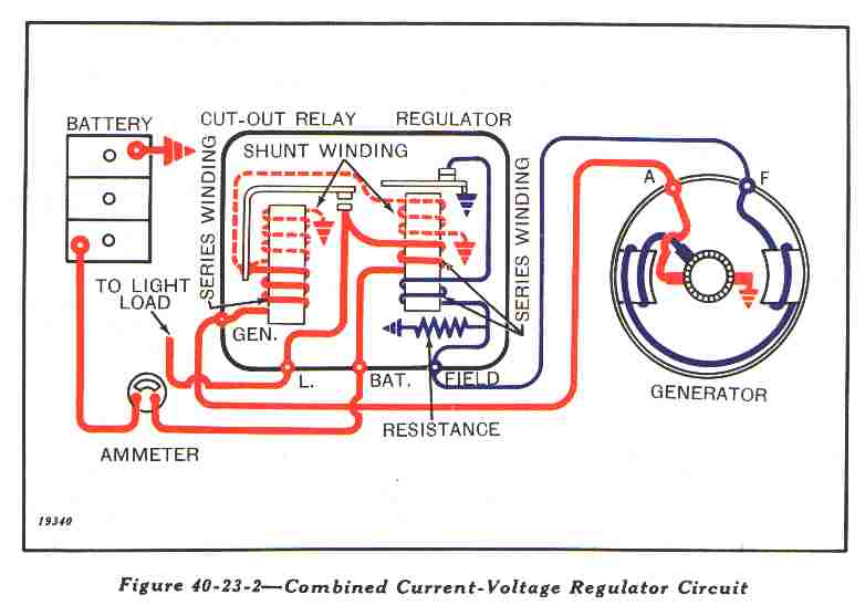
Word pictures are hard, but here goes: Yes, a wire goes from 'F' terminal on the regualator to the 'F' terminal on the generator your regulator is a 'saddle' type, right?-It mounts on the generator itself. If so, There should be a terminal on the bottom that connects to the armature post on the generator.(sometimes marked "A"). A wire from the 'Bat' post on the regulator goes to the ammeter. (It usually works right if you hook to side opposite the +). Two wires come off the other side of the ammeter. One goes to the starter push button, the other goes to the same post on the starter solenoid that the NEGATIVE battery post is hooked to. (The system is positive ground.) The reason the starter button is powered like this is that it can pull 40amps or more when engaging the solenoid and it would peg a 30 amp gauge otherwise. A wire from the 'L' terminal on the regulator goes to the 'BAT' terminal on the 5-position ignition switch. A wire from the 'IGN' on that switch goes to the coil +. For the lights, you're on your own. I usually have to poke around with a test light until I figure out how the resistors work. Don't forget to polarize the generator. I can't remember which posts to cross with a wire, though.
|