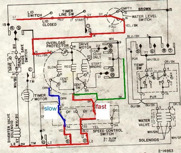
 parrothead, I do believe I would try it like this.. Either leave the existing speed control switch on the back of the motor [if it�s even mounted there] & hard wire into the motor as shown [if you remove the speed control switch you will probably have to hook that black wire that goes to start circuit to the black hi-speed motor connection [see green line],,at present it is hooked to the hi-speed circuit at the speed control switch]...If you want a slower speed try wiring per the blue [slow] line & not the bottom red [fast] line... By looking at the drawing you should be able to hook your 110 AC power wires to the motor"s black & the yellow/black & get high speed.. That motor circuit has more safety switches, & control contacts than a ballistic missile.. There are some concerns by by-passing all those contacts & relays.. My big concern is the possibility of a sneak circuit appearing due to some back feeding of the relays & switches.. Probably the smart thing to do would be to remove all the external switches & relays on the motor & wire directly to the motor�s [yel/blk] & [Blk] wires then hook the start circuit up per the green wire drawn in. Problem is I don�t know how much of that start circuit is internal [obviously the centrifugal switches are] & how much is external in a mounted housing.. I also don�t know how many of the switches & contacts shown are mounted on the motor & how many are remote mounted.. Can you tell if that speed control switch shown in the drawing is mounted on the motor or was it part of the control panel?
I guess a quick power up to the motor�s yel/blk & blk wires will tell you if it is going to motor or not.. Maybe use that 150 watt [or 2 � 100 watt bulbs in parallel side by side] light bulbs in the power wire as a safety until you see what�s going to happen.
It sure would be easier to figure out if the motor was here in front of me.. If this is confusing just post back.. JDClooney@aol.com
|