I'm nearing the end of the cleaning/painting stage
and about to begin assembly of my 1941 9N (12volt,
front dizzy, 9/16 oilpump).
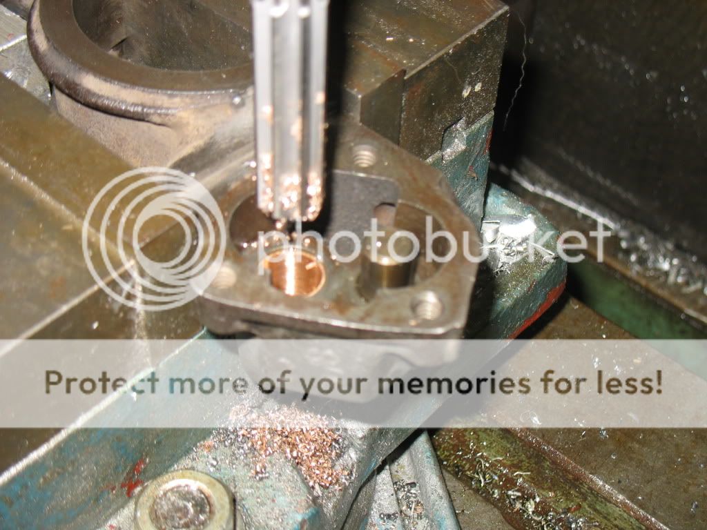
I just had my machinist replace and ream the oil
pump bushing, but three teeth of the new pump gear
hit the housing. We assumed the body moved while
in the mill and we reamed it crooked. Went to get
an oilite brass bushing to try it again, and the
bearing shop owner glances at the original "Ford"-
labelled bushing and mentions that it looks like
the original bushing had more copper and therefore
is harder than the bushing he just sold us.
My first question is: What is the exact dimension
between the two pump shafts?
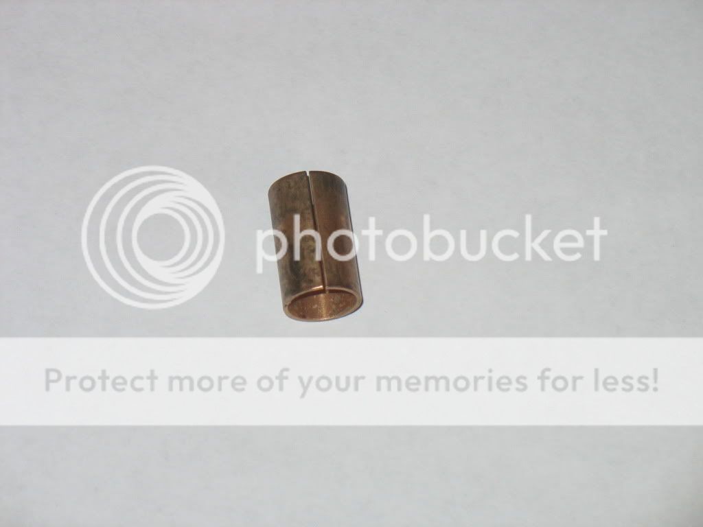
Number two: Why can't we press in some 5/8" OD
copper tube, drill an oil hole, and ream to fit?
Thanks for the help
and about to begin assembly of my 1941 9N (12volt,
front dizzy, 9/16 oilpump).
I just had my machinist replace and ream the oil
pump bushing, but three teeth of the new pump gear
hit the housing. We assumed the body moved while
in the mill and we reamed it crooked. Went to get
an oilite brass bushing to try it again, and the
bearing shop owner glances at the original "Ford"-
labelled bushing and mentions that it looks like
the original bushing had more copper and therefore
is harder than the bushing he just sold us.
My first question is: What is the exact dimension
between the two pump shafts?
Number two: Why can't we press in some 5/8" OD
copper tube, drill an oil hole, and ream to fit?
Thanks for the help
 :0921b879a3]TOH