Generator to alternator conversion

super99

Well-known Member
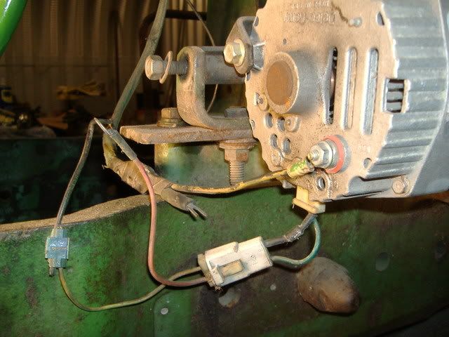
I need some help here. When I tore the Jd 70 down, I took pictures of everything and how it was hooked up so I could just look at pictures and make sure it went back together right. Good idea except the computer got struck by lightning and I lost all the pictures. I am hooking the wiring back up. I think the red wire is not hooked to anything, just taped over. It's a Delco alternator. Anybody know for sure? The wire taped to the yellow wire is dead, leftover from the generator. Just not positive about the red wire. It's hooked into the green wire in the connector, is it a ground wire? Any help appreciated. Chris
JD7012-30-08008.jpg
 
I saw a good post previously on this subject.
Try searching. I would also get rid of those splices and solder the wires and then shrink wrap them. Every break can lead to problems of corosion.
 
<img src = "http://ndtc3500.stellarnet.com/~blweltin/Bob/AlternatorHarness4.jpg">

The wire hanging from the 2-wire connector (Terminal #2) goes to the large output stud to sense voltage.

The wire from the other terminal gets power from the "LOAD" side of the ignition switch, and should have a diode (as shown), a resistor or an "idiot lamp" in-circuit to protect the alternator AND allow the ignition switch to shut down the engine when switched "OFF". In outer words, the diode, idiot lamp, or resistor prevents current from "backfeeding" out the #1 terminal into the ignition circuit at shutdown.

It APPEARS there is a diode covered in heat shrink tubing in the short little harness, so, HOPEFULLY, you are "good to go" in that respect.
 
Well, I'm FLATTERED... I didn't know someone had posted my photo/diagram in the Tractorshed!
 
I'm slightly confused, I don't have a seperate regulator, it is built into the alternator. I'll have to knock some dirt off tomorrow and follow the wires and see, but I think 1 wire goes to ignition switch and the other goes to the amp guage. Chris
 
The diode is there if a idiot light is not used. With the diode or the idiot light it keeps the engine from running after the key is turned off. If the light or diode is not used the alternator will continue to feed the ignition thru the ignition switch and you won't be able to shutt off your engine.

To eleminate the diode and idiot light hook this wire up to the accessory side of your ignition switch.
 
That red wire monitors battery voltage. You can hook it right up to the battery terminal on the alternator if you like or run it thru an idiot light that is powered up with your ignition switch. Or a diode can be put in place of the idiot light. If you hook it to your ignition switch be sure to use an idiot light or diode. If they are not used the alternator will continue to feed the ignition system after you shut the key off and you won't be able to shut off your engine with the ignition switch.
You should be fine though if you hook this wire to the accessory terminal on the ignition switch. I've hooked many of these up this way.
 
Logic would suggest that if it worked properly before, then hook the red wire back to the BAT terminal on the alternator where it was before. That wire is for sensing charge output voltage. It can be hooked to amny different places, but directly to the ALT is the most common.
Should be that simple if you didn't change anything else...

Rod
 
Thank you for repeating what I already posted. After affirming what I posted, you wrote:


"To eleminate the diode and idiot light hook this wire up to the accessory side of your ignition switch."


That's simply DUMB, DUMB, DUMB, as it eliminates the protection to the alternator given by the lamp, resistor or diode. 'Course there's folks like you who have never been in the alternator repair business who have ALL the answers, which will just cost folks more $$$ over the long run.

But, OK, if it makes you feel like you are contributing something USEFUL, HAVE AT IT!

That's what's makes this forum so interesting, folks who don't have a DAMNED clue posting against some of us with extensive experience in the field.


...Bob, alternator repair guy, who PROFITS from the exploits of BLEMS like you.
 
Your over-reaction notwithstanding, I guess I'm missing something here. I thought the purpose of the idiot lite or diode was simply to prevent current from bleeding back through with the ignition off, which it seems would also be accomplished by putting it on the ACC side of the switch. What "protection" are you talking about? And please, answer without calling me an idiot. We all have our individual areas of expertise.
 
If you hook it directly to the battery terminal on the alternator be sure to put a diode in it so it won't drain your battery while it's not running.
 
Glad you feel like I do Mike. Putting the wire on the acc side of the switch will just isolate the alternator out of the circuit all together when the alternator is off. Accomplishes the same thing as the diode.
 
What protection are you talking about? You're not the only one that rebuilds alternators and sorry to hear that you don't like someone repeating what you say.
 
If your so good at what you do, why are you telling him hopefully it is correct by the drawing you've given him.

You explained it correctly and the picture is good but be more positive in your vocabular and learn to spell. You called me dumb!! Remember what they say about those who criticize others.

Seems like you think you are the only one who knows charging systems.

How long you bee rebuilding alternators?? Just curious!
 
You forgot to mention that the idiot light has to be a certian resistance!!!

And you called me Dumb!!!
 
Guys, bear with me on this. What I am talking about is REAL, and I am giving you sound and reasonable advice the MAY prevent trouble and $$$ down the road.

OK, here's the deal... You will NEVER find an OEM GM alternator circuit WITHOUT a resistor or lamp or diode, in the "switched excite circuit" just as I'm trying to explain. AFAIK, the engineers at GM never intended for the alternators to have the #1 terminal directly connected to the battery (though the ignition switch). If someone can find such an OEM diagram, I'll gladly "eat crow". If such an example DOES exist, it is certainly a rarity.

Here is how a diode, idiot lamp, or resistor protect the internal VR and diode trio in case there's a poor connection, resistance/voltage drop in the charging circuit between the alternator's output stud and the battery.

With a DIRECT connection between the alternator's #1 terminal and the battery (though the ACCY side of the ignition switch) if there's ANY voltage drop in the main charging circuit, current will then flow through an alternate path consisting of the diode trio, the internal VR, out the #1 terminal and on to the battery.

The diode trio is only intended to supply probably up to about 4 Amps to "excite" the rotating field, and if it DOES begin to supply charging current though internal wiring in the VR and out the #1 terminal it will overheat/be destroyed and, likely the VR as well.

You may very well GET BY with the "ACCY" hookup, as long as the charging circuit wiring is LARGE, in good shape, and never develops a loose or poor connection.

HOWEVER, choosing to do so opens up a possible "failure mode" for the alternator's diode trio and internal VR that will NOT EXIST if a lamp, resistor or diode are used to limit or eliminate the possibility of current "backfeeding" out of the alternator's #1 terminal.

<img src = "http://ndtc3500.stellarnet.com/~blweltin/Bob/DelcoSIA1A.gif">

<img src = "http://ndtc3500.stellarnet.com/~blweltin/Bob/DelcoSIB1A.gif">
 
There's NO diode needed or used in the lead to the regulator's #2 "voltage sense" terminal.

The #2 wire IS intended to be at battery voltage at ALL times, engine running or not, as it is the "voltage sense" lead. It will NOT drain the battery.

It is the #1 terminal that MUST be powered down at engine shutdown.

Installing a diode in the lead to the #2 in the reverse-biased position would result in NO voltage sensing and the alternator OVERCHARGING by at least a couple of Volts.

Installing a diode in the lead to the #2 in the forward-biased position would drop the voltage to the #2 terminal by the voltage drop across a silicon semiconductor junction (about 0.6 Volts)
causing the regulator to increase the charging voltage by about that amount. (0.6 Volts above the regulator's normal setpoint.)
 
The problem is NOT completely isolating the alternator when the ignition switch is "OFF". The problem is the alternate charging path to the battery though the ACCY terminal during normal operation, when the ignition switch is "ON" and the engine is running/alternator charging.
 
Again, logic would dictate that the red wire shown is the sensing wire, and that's hooked directly to the BAT terminal. No diode, no fuse, no bulb. Nothing. Just a plain, simple, tight connection.
The other wire shown feeds into the harness so I'd assume that it's hooked to an idiot light or some other arrangement elsewhere.

Regardless, I don't worry too much about whether it's got a diode or light. I've hooked them up direct through pressure switches and also bundled the two wires directly to the BAT terminal. Both worked without problems.... except that when both were wired to the BAT terminal, the tractor had to run every couple days to keep the battery up. It will discharge like that. Conversly, if you had a ground master disconnect it wouldn't matter either.

There's lots of ways to hook those things up so that they will work fine. One should run the excite wire through a diode or preferably a 194 bulb, but I wouldn't sweat it in an emergency.

Back to the original question.... the guy removed the wiring to do some other work. I assume the thing charged correctly before. The red wire belongs on the BAT terminal. Put it back there and don't worry about it.

Rod
 

We sell tractor parts! We have the parts you need to repair your tractor - the right parts. Our low prices and years of research make us your best choice when you need parts. Shop Online Today.

Back
Top