
Geo-TH,In
Well-known Member
Yesterday I had too
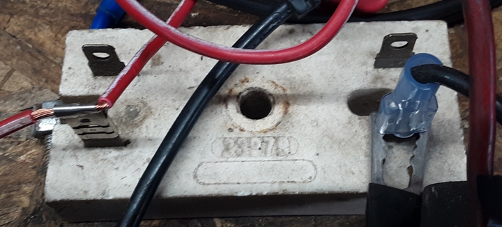
much time on my hands. I found a ballast resistor that may have been used on a Dodge Aspen Mopars first generation electronic
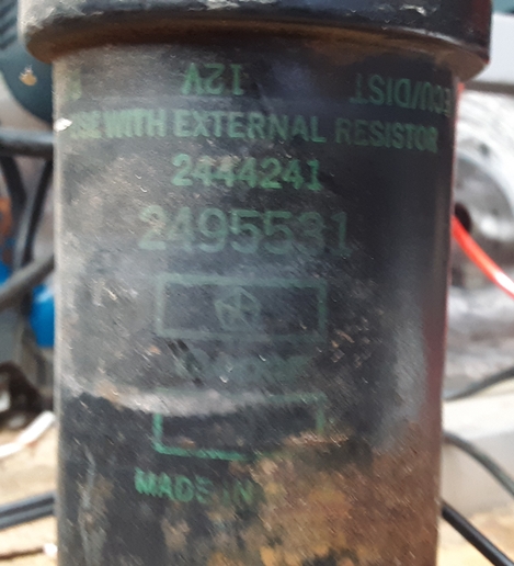
ignition. I found a 12v coil. All the used parts are in a drawer dedicated to my Jubilee's parts drawer.
So I made a series circuit, a ballast resistor on the left, a HF 10 amp meter going between the ballast and the 12v coil.

The circuit is connected to a 12v mower battery which the midtronics meter shows 12.78v. The battery was recently charged.
The HF meter on the left is showing a - 4.97v, the ballast voltage. I should have reversed the wires to meter, but who cares.
The middle HF meter is reading 3.86 amps.
The right HF meter is showing the coil voltage is 6.17v.
I ran out of HF meters or I would have measured the volts used by the wires and the ammeter.
The wire on the right is a 16g wire.
The wire on the left is the hair like wires the 4 amps is going through to the ammeter, the center meter.
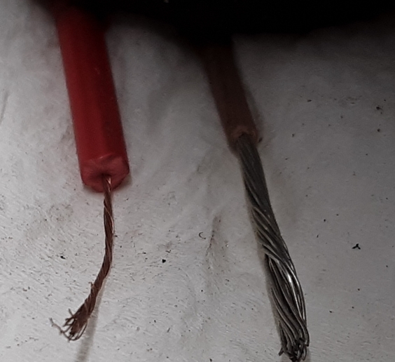
Those who are sharp enough will soon ask, where is the missing voltage? Good question. I think part of the problem is meter accuracy, and some of the missing voltage is used by the ammeter and the hair like wires used by the meter.
My objective is to find a used coil and ballast resistor for my Jubilee. My son wants the tractor after I'm gone. He wouldn't have a clue what coil and ballast to buy.
When I have more time to kill. I plan to take the coil off the jubilee and use it in my experiment. If the coil off the Jubilee uses 6v and 4 amps, I would conclude the coils are the same. The coil have a 1.5 ohm primary resistance
If I have 4 amps and 6 volts going to the coil, I'm happy regardless if I have missing voltage.
For all those familiar with Ohm's law. 4 amps and 12v means 3 ohms total is the series circuit. Ballast 1.5 ohms and coil 1.5 ohms = 3 ohms. Does anyone have an ohmmeter that can accurately measure 1.5 ohms plus or minus 1% or 2%? I should ask can anyone afford an ohmmeter that can accurately measure 1.5 ohms plus or minus 1 or 2%?
So much for my round 2 it experiment.
This experiment shows the importance of having accurate and calibrated meters, which obviously I don't have.
I'll let all the EEs answer the questions. I'm sure JohnT and Mark would love to field questions.
You-alls have a good day. Is You-alls plural?
much time on my hands. I found a ballast resistor that may have been used on a Dodge Aspen Mopars first generation electronic
ignition. I found a 12v coil. All the used parts are in a drawer dedicated to my Jubilee's parts drawer.
So I made a series circuit, a ballast resistor on the left, a HF 10 amp meter going between the ballast and the 12v coil.
The circuit is connected to a 12v mower battery which the midtronics meter shows 12.78v. The battery was recently charged.
The HF meter on the left is showing a - 4.97v, the ballast voltage. I should have reversed the wires to meter, but who cares.
The middle HF meter is reading 3.86 amps.
The right HF meter is showing the coil voltage is 6.17v.
I ran out of HF meters or I would have measured the volts used by the wires and the ammeter.
The wire on the right is a 16g wire.
The wire on the left is the hair like wires the 4 amps is going through to the ammeter, the center meter.
Those who are sharp enough will soon ask, where is the missing voltage? Good question. I think part of the problem is meter accuracy, and some of the missing voltage is used by the ammeter and the hair like wires used by the meter.
My objective is to find a used coil and ballast resistor for my Jubilee. My son wants the tractor after I'm gone. He wouldn't have a clue what coil and ballast to buy.
When I have more time to kill. I plan to take the coil off the jubilee and use it in my experiment. If the coil off the Jubilee uses 6v and 4 amps, I would conclude the coils are the same. The coil have a 1.5 ohm primary resistance
If I have 4 amps and 6 volts going to the coil, I'm happy regardless if I have missing voltage.
For all those familiar with Ohm's law. 4 amps and 12v means 3 ohms total is the series circuit. Ballast 1.5 ohms and coil 1.5 ohms = 3 ohms. Does anyone have an ohmmeter that can accurately measure 1.5 ohms plus or minus 1% or 2%? I should ask can anyone afford an ohmmeter that can accurately measure 1.5 ohms plus or minus 1 or 2%?
So much for my round 2 it experiment.
This experiment shows the importance of having accurate and calibrated meters, which obviously I don't have.
I'll let all the EEs answer the questions. I'm sure JohnT and Mark would love to field questions.
You-alls have a good day. Is You-alls plural?