Nippon Denso Alternator for 6V to 12V ???

Crazy Horse

Well-known Member
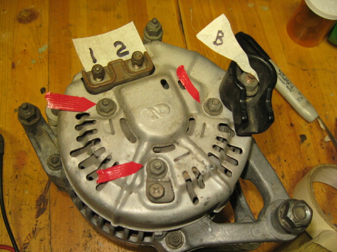
I have a small, compact Nippon Denso alternator here in working order (series 5685) that came from an early 90's Jeep. I was thinking it's maybe a candidate for a 12V conversion on a 1940's 6V tractor. I know most conversions favor certain GM one-wire alternators, this smaller one I have would be my preference for size alone. So first, I guess one would call it a 3-wire alternator right? I am also assuming (hoping) it has a built in regulator of some kind for charge control. See the picture below of the one I have here.

The one big heavy terminal tagged B would obviously be the one from the battery's positive post, the three locations that are red-tagged aren't really wiring terminals, they hold the end cover on & go to ground. But one has a threaded terminal immediately next to it where a wire could be grounded if needed.

My question relates to the two nut-type terminals that are marked 1 & 2 in the picture. Neither one is stamped with a number or a letter of any kind next to it on the alternator.

Is this a candidate for a simple 12V conversion? Any advice or help is appreciated along with a diagram if someone has one they could post.
cvphoto120257.jpg
 
What I'm finding shoes that to be an externally reregulated alternator.

The 1 and 2 terminals are each end of the field winding.

You can still use it, but would need to add a regulator, as in an early Chrysler electronic regulator.
Wiring
 
Thanks Steve, that is quite a series of photos and wiring diagrams. So it would seem that the 2 smaller hook up wires could in fact go to either of the two terminals, unless positionally left and right have any meaning? What source is all of that from?

I should mention that my Haynes manual for my Jeep (91 YJ 4 cylinder) indicates some Jeeps used a Delco alternator and others the Nippon Denso. It starts the section on alternators (before later saying there were two kinds used) with the statement ..... 'The charging system includes the alternator, an internal voltage regulator, a charge indicator, a battery, a fusible link and the wiring between all components.'

In the big wiring diagram in the manual, I can't find any external voltage regulator but that diagram doesn't seem to refer to the Nippon Denso unit since it shows an alternator with the one big lead from the battery and then three smaller wires to 3 terminals labelled A,B, and C.

I'm sure the info you found is the correct stuff, I must search inside my engine compartment for that external voltage regulator that appears in your information.
 
From Alldata,
The engine controller controls the alternator's field ground based on how close the battery sense voltage is to the voltage goal. If the battery sense voltage is below the voltage goal, the engine controller initiates the grounding of the field. If the battery sense voltage is above the voltage goal, the module stops grounding the field, thus effectively disabling the magnet and stopping output.

mvphoto89375.png

mvphoto89378.png

The regulator Steve has pictured will work but needs to be bolted to ground to function.
It appears the DG or DB is switched 12v and the TN/BK is regulated ground from the voltage regulator.
 
(quoted from post at 09:37:37 03/16/22) From Alldata,
The engine controller controls the alternator's field ground based on how close the battery sense voltage is to the voltage goal. If the battery sense voltage is below the voltage goal, the engine controller initiates the grounding of the field. If the battery sense voltage is above the voltage goal, the module stops grounding the field, thus effectively disabling the magnet and stopping output.

mvphoto89375.png

mvphoto89378.png

The regulator Steve has pictured will work but needs to be bolted to ground to function.
It appears the DG or DB is switched 12v and the TN/BK is regulated ground from the voltage regulator.
s this a generic diagram, or specific to his particular model Jeep?
 
I think I got it figured out, with your help of course. If I were to use this alternator on a tractor 12V conversion, I would have to buy one of those remote regulators (or the kit with one in it) and wire it up like the link you sent me showed. Apparently the blue and green wires in that diagram are reversible (to either of those two field terminals) and the 12V power into the regulator should arrive through a switch which is on when you are starting or using the tractor.
 
I expect polarity through the field winding is important.
Note that switched 12v is wired to to the alt at the small terminal (DG) farthest from the output to battery terminal , and the other small terminal (tan black wire) is the negative wire from the regulator. The regulator varies potential to ground to control alt output with the tan black wire. The factory harness on your Jeep is wired properly, use that diagram as a guide to wire the regulator to the alternator on the tractor. Standard Ignition 12 Volt Voltage Regulator STD VR125 Voltage Regulator Connector
Connector Used With STD VR125
mvphoto89467.png

mvphoto89468.jpg


mvphoto89469.jpg


This post was edited by racered57 on 03/17/2022 at 04:01 pm.
 

We sell tractor parts! We have the parts you need to repair your tractor - the right parts. Our low prices and years of research make us your best choice when you need parts. Shop Online Today.

Back
Top