Cub generator

grandpa Love

Well-known Member
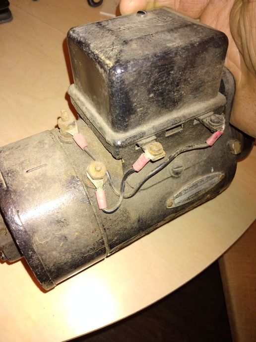
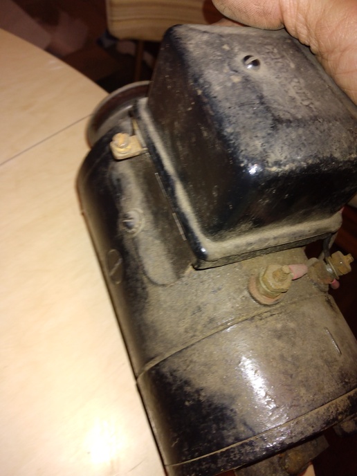
Just picked this up today. How do I wire it? Tractor has a magneto and no multi position light switch. The cut out has 2 studs on one side, one on the other. I'm struggling to find a correct diagram. Any help appreciated!
cvphoto118890.jpg


cvphoto118891.jpg
 
I'm NOT sure why I am taking the time to type this as you likely won't read it through, much less install the generator as I suggest, and give it a try, by here goes...

That specific cutout is rather unique in that it has a field resistor inside similar to the field resistors found on some light switches.

The way the setup is wired NOW is correct for a tractor without a light switch, the "F" terminal on the generator is connected to the "F" terminal on the cutout, making use of the internal field resistor.

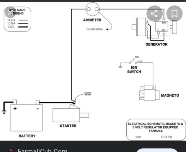
(Note the diagram posted by Rodney shows the "F" terminal on the cutout UNUSED, as the light switch is present and it's resistor is used INSTEAD of the one in the cutout.)

All you need to do is connect the BATT terminal on the cutout (the one with nothing currently connected to it) to the tractor's Ammeter and on to the battery and (if the generator and cutout are functional) it will charge at a low rate, just fine for a tractor with no lights.

Polarize the generator BEFORE startup by momentarily jumpering the BATT and ARM terminals on the cutout.

This is a "third brush generator" and the charging rate (with the field resistor in the circuit) is fine-tuned by the position of the third brush.
 
Grandpa, iffffffffffff that's the correct cutout relay for the genny upon which its mounted ?? WHICH I BELIEVE IT MAY BE it already has what I assume (NO warranty absent more info) the correct wiring IE the relays GEN/ARM terminal is wired to the gennys ARM (often bigger then FLD) post and the relays FLD terminal is wired to the gennys FLD (often smaller then ARM) post. Ifffffffffff thats what it is ???? the other unused relay terminal (marked BAT perhaps ??) would wire to the LOAD (NOT battery/starter Supply) side of an ammeter.

Some of the older Farmalls (such as F series etc) didnt use any light switch type Low High manual charge and that was long before the 4 position LHDB light switch use. Instead the Field got its ground through a resistor inside the relay VERSUS the 4 position Low High light switch where the FLD post was wired to the switch and it got a dead ground for High charge but via a resistor for Low charge

NOTE Im NOT any old Farmall charging expert, so if they post see what Bob M or Janicholson have to say. Even if that genny and relay will work I didnt think the Cub series used that set up BUT I DONT KNOW ask Bob M or Janicholson

John T thats my best pure GUESS for now until the Farmall experts arrive
 
Wore out, I did read it! And it sounds
like you have it figured out. I hope to
get this installed today! Thanks, Kevin
 
Yayyyyyyyy congratulations and thanks for the feedback, that was my best guess but I didn't have that schematic whewwwwwwww lol

John T Not any Farmall expert
 
I did! But the image hosting site (Epson Photo) disappeared several years ago.

As time permits I'll upload the diagrams to my Flickr image site and share the link.
 

We sell tractor parts! We have the parts you need to repair your tractor - the right parts. Our low prices and years of research make us your best choice when you need parts. Shop Online Today.

Back
Top