706 loader remote issues

Samualh

New User
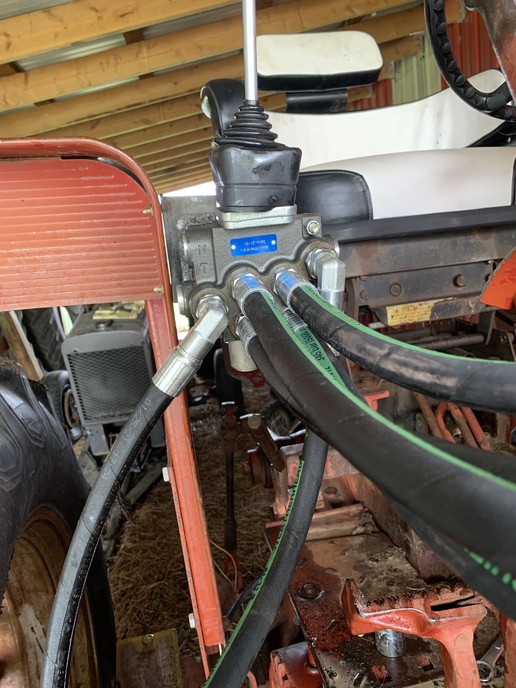
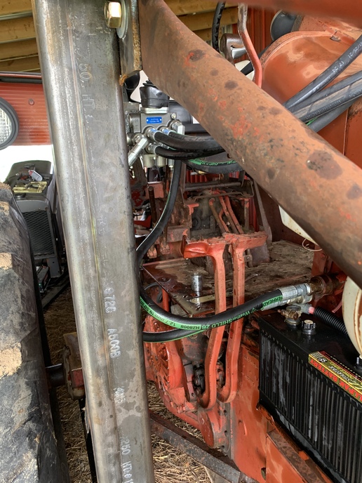
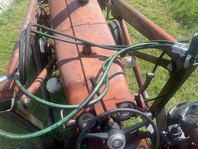
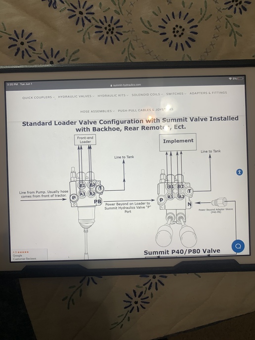
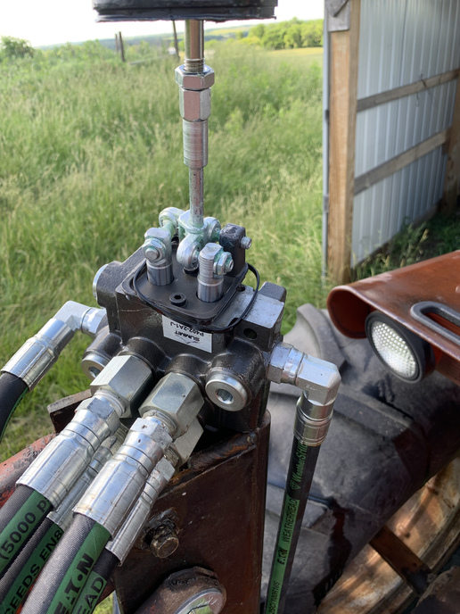
Hi Im working on a farmall 706 and I have just put a duall loader on the tractor and am plumbing up hydraulics, I have bought a 2 spool joystick directional control valve and am very confused on what Im doing wrong, rn I have it running off one of the auxiliary remotes on the tractor on what I thought would be and open center system on the auxiliary ports on the right side of the tractor. If I have the auxiliary lever on the tractor pulled towards me the loader falls both directions the joystick is pushed, if I have the axillary lever forward the loader only rises both directions the lever is pushed. If anyone has any ideas for whats going on please help
 

cvphoto91044.jpg


cvphoto91045.jpg
 
Hello Sam welcome to YT! In your photo if I see it right you have 4 outlet function ports, Side by side, stacked in two pairs one above the other. So do the two right pair going to a single function? As an example the top of the right pair raises the main loader frame and the bottom of the right pair goes to lower it? Just as an example could be the left pair. Judging by the silver spool covers I see out the bottom of the valve this is my assumption of how it should connect. Is there a diagram with the valve that instructs you as to the proper connections?
 
The right pair runs to the lift function of the loader while the left pair runs to the tilt function of the loader, I know that these are hooked up correctly based on the diagram sent from the manufacturer, the cylinders are double acting and the joystick is designed for that function
cvphoto91047.jpg


cvphoto91048.jpg
 
So you're saying that if you push the lever straight forward, the loader goes up, and if you pull it straight back, the loader ALSO goes up??? That makes no sense unless the valve is the wrong one or is somehow faulty.

If you had it hooked up wrong it wouldn't even do that much. That is if you had things crossed the oil would have nowhere to go and the tractor would just sit there and squeal.
 
I have an IH power beyond cover that bolts on the original valve body to feed your valve .Been sitting 35 years and could send it. S WI.
 
Have you used this loader before or did you see it work before you put it on the tractor? The piston nut will screw off the end of the piston rod and make the loader do funny things on those Du-al loaders. Might not be the problem right now but it might do this to you sometime in the future. Use loctite when you screw the nut back on TIGHT.

It still sounds to me like you have some hoses mixed up. I have run into something similar to this when I hook the hoses back up wrong when I put the quick tack loader back on.
 
What I would try is to rotate the 4 function/outlet hoses 1 port right or left and see if it works properly. It seems like I one time re-hooked up a loader and it acted similar to what yours is doing. Turned out as I recall, the hoses were not correctly positioned. Mark.
 
Are the ports on the valve labeled?

Typically they will be labeled:

P Pump or pressure

T Tank return

A or CYL

B or CYL

Get the P and T right, it should work. If backward reverse A and B.
 
Ok, no go on the call. I will change that to say email me a phone number and I can help you after 6:30 pm central tomorrow. But meanwhile, it should be obvious the position of the tractor remote that gave raise motion is the correct position. I agree, FIRST if you have not operated the loader direct from the tractor remotes I would suggest doing that with that set of quick couplers you have. Remember how they are connected now so you can put it back the same. Next I would suggest contacting the seller of the valve to get some assistance on the issue you are having, I would get details from them exactly what should be done with the power beyond section of the valve when connecting through the remotes as you are. If this is an eBay valve or the like where no technical assistance is available here is what I would suggest. Disconnect all the hoses from the valve. Get you a source of compressed air flow at a rate equal to a tire valve stem when removed at 15 psi. Direct this in the inlet pressure port of the valve, connecting it via pipe adapters would be ideal.Then operate the valve making sure only one spool is moving. When a spool is moved one direction it should only flow air out of 1 of the 4 center ports. Move the same spool the opposite direction and note which one the air flows from then you have one pair determined. Continue with the other spool which should provide the same results with the remaining pair of output ports. If you test the loader functions direct off the tractor remotes. And the valve supplies oil to only one port when one spool is moved and you connect your two functions to the output ports as determined by the air flow test it should work. The only other thing I would mention is if the valve can be converted to a closed center valve? If it is an either or is it configured properly for open center operation? Usually a plug is installed in an internal passage to convert to closed center system. Per your description I do not think that is the problem but worth checking.
 
Looking at the picture with the aerial view so to speak. It looks like you have the 2 top hoses running to one function and the bottom 2 hoses running to the other function. If this is correct then you need to switch some hoses. You need the hoses to be per the picture you posted where the A1 and B1 ports are one function and A2 and B2 ports are the second function.
Oil flow needs to go from the pressure port to a line teed to both lift cylinders and the return needs to be the same then like wise for the bucket. The A and B, 1 and 2 are per your picture supplied.
 
(quoted from post at 06:02:44 06/08/21) Looking at the picture with the aerial view so to speak. It looks like you have the 2 top hoses running to one function and the bottom 2 hoses running to the other function. If this is correct then you need to switch some hoses. You need the hoses to be per the picture you posted where the A1 and B1 ports are one function and A2 and B2 ports are the second function.
Oil flow needs to go from the pressure port to a line teed to both lift cylinders and the return needs to be the same then like wise for the bucket. The A and B, 1 and 2 are per your picture supplied.

I'm no expert but I see the same thing. Each pair should be set up vertically on the valve and not horizontally.
 

We sell tractor parts! We have the parts you need to repair your tractor - the right parts. Our low prices and years of research make us your best choice when you need parts. Shop Online Today.

Back
Top