CapayMiller
Member
Hi all,
I acquired a solid JD 4010 last August to replace my beloved 4020 that was incinerated in a fire in June. The 4010 has a 12v alternator and 2 12v batteries, but benefits from a 24v starter which spins it
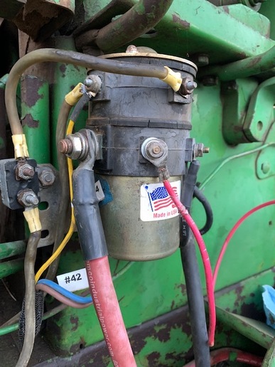
like no one's business. Instant starts. The tractor has a Delco Remy 119845 1500A starter relay, that combines the 2 12v batteries to provide 24v to the starter, but reverts to 12v once running.
When I reassembled the dash after replacing the steering valve my electrics were non-functional. The original wiring was in pitiful shape, so I installed a new harness. All good, except for the one wire
that controls the battery combiner relay. I stupidly failed to trace all the connections prior to disassembly, so am not sure where the signal that controls the combiner relay originated.
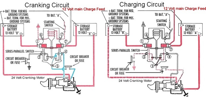
According to a diagram supplied by Texas Industrial Electric Co., the starter signal should go to Terminal 7 on the relay from BAT-A on the starter switch. When I do that, however, the relay doesn't
energize and the 12v going through the starter isn't enough to start things. HOWEVER, when I connect to the ST terminal on the starter (key) switch, it spins and starts right up. However, for some
reason the relay doesn't de-energize, so the starter continues to spin after I return the key to the "run" position.
According to the diagram, and helpful Sharpie numbers the P.O. put on the solenoid, everything looks connected appropriately to the terminals indicated in the TX Industrial wiring diagram. When I
connect Terminal 7 to anything other than the ST terminal on the starter switch, I only get 12v to the starter. When I connect it to the ST terminal the starter spins with 24v, but doesn't stop spinning.
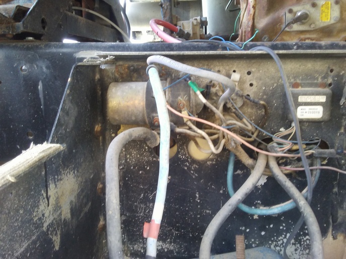
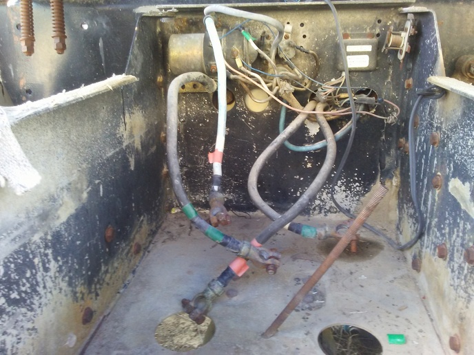
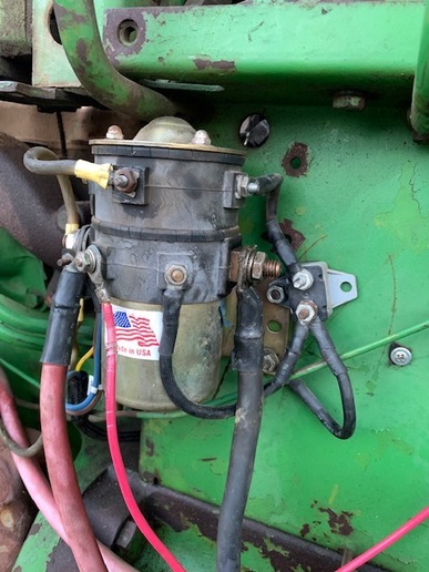
In the photos: The yellow wire is the signal wire from the starter switch, going to the "live" side of the relay. The red lead on the smaller terminal waist-high *should* be the trigger circuit to close the
relay, and *should* go to BAT-A according to the Texas Industrial wiring diagram. However, I only get the relay closing (but not opening) when I connect the red lead to ST on the starter switch. All the
leads in the 2nd photo (right side looking at the relay) lead to ground.
Any guidance from the crowd??
Thanks for the Wisdom of the Crowd.
- David in CA.
I acquired a solid JD 4010 last August to replace my beloved 4020 that was incinerated in a fire in June. The 4010 has a 12v alternator and 2 12v batteries, but benefits from a 24v starter which spins it
like no one's business. Instant starts. The tractor has a Delco Remy 119845 1500A starter relay, that combines the 2 12v batteries to provide 24v to the starter, but reverts to 12v once running.
When I reassembled the dash after replacing the steering valve my electrics were non-functional. The original wiring was in pitiful shape, so I installed a new harness. All good, except for the one wire
that controls the battery combiner relay. I stupidly failed to trace all the connections prior to disassembly, so am not sure where the signal that controls the combiner relay originated.
According to a diagram supplied by Texas Industrial Electric Co., the starter signal should go to Terminal 7 on the relay from BAT-A on the starter switch. When I do that, however, the relay doesn't
energize and the 12v going through the starter isn't enough to start things. HOWEVER, when I connect to the ST terminal on the starter (key) switch, it spins and starts right up. However, for some
reason the relay doesn't de-energize, so the starter continues to spin after I return the key to the "run" position.
According to the diagram, and helpful Sharpie numbers the P.O. put on the solenoid, everything looks connected appropriately to the terminals indicated in the TX Industrial wiring diagram. When I
connect Terminal 7 to anything other than the ST terminal on the starter switch, I only get 12v to the starter. When I connect it to the ST terminal the starter spins with 24v, but doesn't stop spinning.
In the photos: The yellow wire is the signal wire from the starter switch, going to the "live" side of the relay. The red lead on the smaller terminal waist-high *should* be the trigger circuit to close the
relay, and *should* go to BAT-A according to the Texas Industrial wiring diagram. However, I only get the relay closing (but not opening) when I connect the red lead to ST on the starter switch. All the
leads in the 2nd photo (right side looking at the relay) lead to ground.
Any guidance from the crowd??
Thanks for the Wisdom of the Crowd.
- David in CA.