Kohler gen., 1967, what do you call this type of transformer

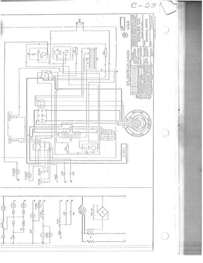
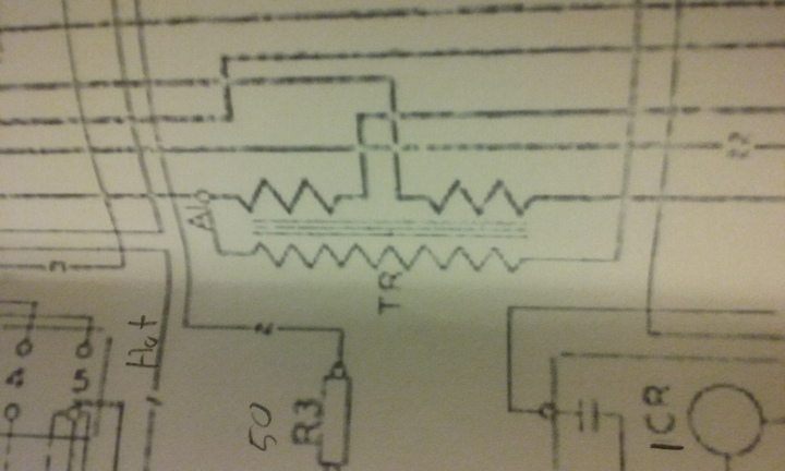
I posted on the Smokstak forum, asking for information on what you called this type of transformer, but did not get an acceptable answer. I know that some of you guys are electrical engineers. This transformer takes the two legs of 120 volt output and feeds it into the middle of the transformer, presumably to equalize the losses, then the secondary side feeds into a selenium rectifier to power the exciters. Anyway, I have searched the world wide web and have not been able to find a schematic like the one here.

I am just curious, trying to learn about my generator.
cvphoto19213.jpg
 
> Dual secondary auto transformer.

Not an autotransformer. An autotransformer has only a single winding with multiple taps that serves as both primary and secondary winding.

Dual secondary, yes. The question, of course, is "what are the output voltages of each winding?".
 
I'm not an engineer, but I am pretty sure that the dual part is on the primary side, and the single is on the secondary side. The secondary goes into a selenium rectifier and has a very low current flow. I know that it is not a center tap transformer. Thanks.
 
Hi Billy, I'm out of town for a few days. All I was wanting to know is what the name of that type of transformer is so that I can read up on it.
 
> I'm not an engineer, but I am pretty sure that the dual part is on the primary side, and the single is on the secondary side. The secondary goes into a selenium rectifier and has a very low current flow. I know that it is not a center tap transformer. Thanks.

It's pretty unlikely to have dual primary windings. But one of the secondary windings may be shown on the same side as the primary.

It's possible the extra secondary is used to power control circuitry.
 
> This transformer takes the two legs of 120 volt output and feeds it into the middle of the transformer, then the secondary side feeds into a selenium rectifier to power the exciters.

OK, I re-read your original post and it makes a bit more sense now. That transformer may be intended to shift the phase angle of the ac voltage going to the rectifier, possibly to reduce distortion of the generator output. Hard to say with just part of the schematic.
 
How about showing the whole schematic. TR symbology usually is a coil whereas what's indicated is normally a resistor. Terminal A1 seems to be a neutral reference for the transformer primary and one secondary, assume it to be the long "resistor" symbology with the transformer having 2 secondaries, the small ones with one referenced to N at terminal A1 and the other floating. At least they got the "core" symbol correct.

The small one on the left could power control circuits and the one on the right could go to a bridge rectifier providing the hi power output whereby a pair of diodes of that bridge would tie back to the A1 or N terminal and the other two would be tied to the load filter capacitors, maybe inductive input (LC circuit) and output power to the regulator device(s)....controlled by power from the "control" winding. Again seeing the whole thing would help.
 
besides poor print quality, I say that left side which is cut off would be much more helpful that the part shown. Schematic vs interconnect diagram.
 
(quoted from post at 11:16:06 04/08/19) besides poor print quality, I say that left side which is cut off would be much more helpful that the part shown. Schematic vs interconnect diagram.

Q4jQQY7.jpg


Looks to me that it's a sort of "current transformer" that adds power to the rectifier circuit powering the stator/field coils as the load on the generator increases, basically acting as a simple voltage regulator.

Can't see clearly enough, but it appears the generator output current passes through the two "primaries" in the transformer.

Must be some heavy-duty stuff!
 
Bob, thanks for the reply. Yes, it is some
sort of simple, durable, voltage regulating
system. I am just trying to find out what
the transformer is called so I can research
how it works.
 
(quoted from post at 12:18:11 04/08/19) Bob, thanks for the reply. Yes, it is some
sort of simple, durable, voltage regulating
system. I am just trying to find out what
the transformer is called so I can research
how it works.

Well, I think "current transformer" is a good search term to check out.

Was my assumption that the primary windings are heavy wire correct?
 
(quoted from post at 13:16:52 04/08/19) Yes, very heavy. It is a 6.5 KW, 120-120
single phase.

I was not talking about "weight".

My specific question would be if you have located/identified the transformer in question, and if, in fact, the primaries are wound with wire heavy enough to carry the generator's output current.
 
Yes, I can look right at the transformer.
It is about 5" tall, and 4 inches thick.
100% of the output runs through the
transformer. The wires are maybe 6 guage.
The wire on the secondary is maybe a 14
guage
cvphoto19279.jpg
 
The answer you were given by Vanman on the Smokstak forum appears to be correct. Compound or compounding transformer. Can't tell for sure since I cannot see the schematic clear enough.
 
OK. Thanks to the help here, I had a few more terms to Google. The transformer is called an "instrument" or "current" transformer. It's job is to step down the voltage by a predetermined amount that will always be proportional to the current transferred to the load. If the load goes up then the current in the secondaries increases, which then goes to the rectifier, turned into DC, then off to the exciters to increase voltage. Within limits it makes the voltage self-regulating.

I have not been able to find a picture of a transformer that has the input going to the center of the windings then out to the edges. I think that is to send smoother waves to the rectifier. Still researching.
 
(quoted from post at 21:09:58 04/08/19) OK. Thanks to the help here, I had a few more terms to Google. The transformer is called an "instrument" or "current" transformer. It's job is to step down the voltage by a predetermined amount that will always be proportional to the current transferred to the load. If the load goes up then the current in the secondaries increases, which then goes to the rectifier, turned into DC, then off to the exciters to increase voltage. Within limits it makes the voltage self-regulating.

I have not been able to find a picture of a transformer that has the input going to the center of the windings then out to the edges. I think that is to send smoother waves to the rectifier. Still researching.

"input going to the center of the windings then out to the edges. I think that is to send smoother waves to the rectifier."

I'm pretty sure are overthinking that part.

Of course, primary windings would have to be connected so the magnetic field they produce is additive to each other (not cancelling each other) and the secondary has to be connected "in phase" with the output lead connected to it, so as to ADD to the voltage being sent to the rectifier as load increases.
 
" I am just trying to find out what
the transformer is called so I can research
how it works. "

It would help if you had access to the transformer specification. With that you could obtain the turns ratios and wire sizes used which would aid you in your quest. Voltage applications tend to be smaller wire and more turns. Current applications are few turns of large wire...usually.

As others have said, complexity of this transformer is to aid in regulating the output under varying conditions and to do that you have to have "sense" windings, sensing output voltage and currents to feed "load" information to the regulating circuitry for it to function.

Thanks for the schematic but really hard to read as you can tell. I was able to detect the bridge rectifier and the Armature and Field terminal blocks for the generator proper.
 

A generator will typically use a compound transformer if it is transformer regulated. A compound transformer is a combined potential or voltage unit and a current transformer all in one. The primary will have a thick winding in series with the output which is the current part of the transformer, the other primary winding will be in parallel with the output and will be a much finer winding. That is the voltage part of the transformer. This type of transformer will show two separate windings for the primary as in your schematic. They often have an adjustable shunt to adjust the voltage. They also are often a leaky or lossy transformer so as to be non-linear at higher currents. Standard current transformers would typically be linear.

It is possible that you have a current transformer only but a combined or compound type would be more common for this application. A good schematic or even the model number would help.
 
Guys, thanks for hanging in there. My name plate is sort of messed up, but the model is 6.5???, the spec# is 5066A, and the controller # is A-245701.

I did not realize this was so complicated, but I am happy to be learning from you all.
cvphoto19397.jpg


cvphoto19398.png
 

From similar schematic for a slightly smaller model, the transformer appears to be only a current transformer not a compound transformer but an ohm meter will show which one it is. Not necessary the best way to achieve regulation but they do work and are simple.
 

We sell tractor parts! We have the parts you need to repair your tractor - the right parts. Our low prices and years of research make us your best choice when you need parts. Shop Online Today.

Back
Top