electrical 12 volt expert needed

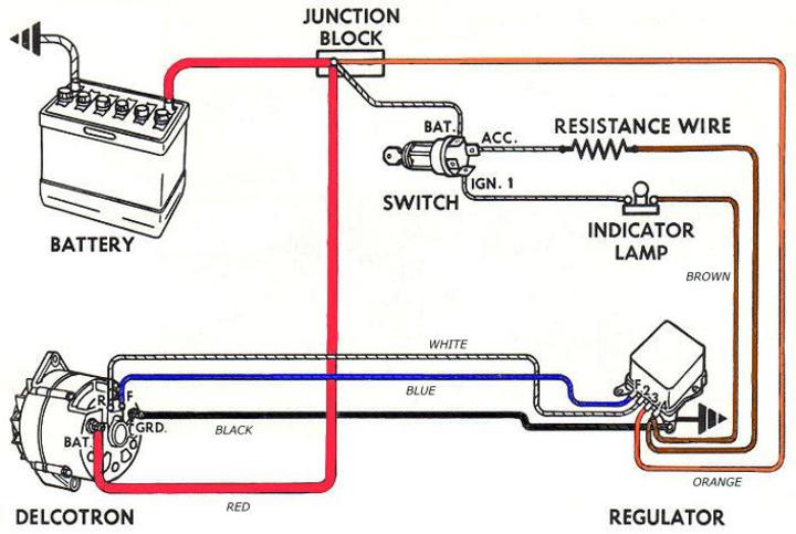
I am working on some wires on a NH selfpropelled baler and it has a wire coming from the F terminal of the voltage regulator going to the alternator but right after the VR the wire splits and one goes up to the cab like it is supposed to connect to the ignition switch or something but it was not hooked up and the connection looks like it was that way from the factory but the wiring diagram does not show it. Where would it go and why is it there? Also this is a ford 240 industrial engine and it has a resistor in line going to the coil and that is the way it is in the book but can the coil be replaced with a coil that has a internal resistor and it is all 12 volt. Thanks
 
The extra wire can be removed. (opinon) The coil can be replaced with a 12v coil for use without an external resistor. There are no resistors inside coils, they are just designed to run on 14+ volts, instead of about 6 volts common with a resistor required coil. If there is an "I" terminal on the starter relay (solenoid) it will make it a better starting engine if that "I" terminal is connected with 14 gauge wire to the coil side of the resistor in place now, or a new coil with external resistor required. This "I" terminal bypasses the resistor and gives the coil cranking voltage to boost output to the plugs while cranking. Jim
 
The wire from the F terminal, are you sure it is the F terminal, and not the S terminal?

I've seen the S (stator) wire used to power an accessory that only gets power when the engine is actually running, like an electric choke, hour meter, etc.

I've never seen the F (field) connected to anything other than the alternator to regulator. If it's not connected, I would not worry about it. Could be a mistake in the harness, could be an unused circuit, very common to have dead end wires.

As for the coil, if you want to do away with the resistor wire, then yes, you can use a coil wound to operate on full 12 volts. But if the resistor wire is staying, you need to keep a coil wound for use with an external resistor.
 
Here is a wiring diagram for a ford alt w/external regulator
a250387.jpg
 
In some installations of older alternators with remote regulator the extra field wire is used to illuminate the charging indicator lamp on the dash. That's why the line goes up to the panel area. When the key is on, but engine not running, there is 12V to the field wire, but the other end is not excited. Once the engine is started, and the field wire is energized, the 12V appears on both sides of the lamp, and it is not lit.

You do not need it, unless you want to have a charging indicator on the dash.
 
Thanks everybody for the advice it has a amp guage so I will not hook that wire up to anything and the coil I will leave it like it is for now and it does have a wire to run from the I side of the solenoid to the coil hopefully that will make it start better it was very difficult to start and somebody had just wired it so it would crank and run that was about all but trying to get everything back to original. THANKS
 

We sell tractor parts! We have the parts you need to repair your tractor - the right parts. Our low prices and years of research make us your best choice when you need parts. Shop Online Today.

Back
Top