1947 John Deere Model B eiring

Lon Franklin

New User
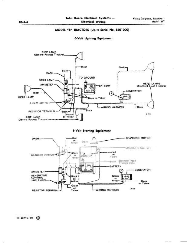
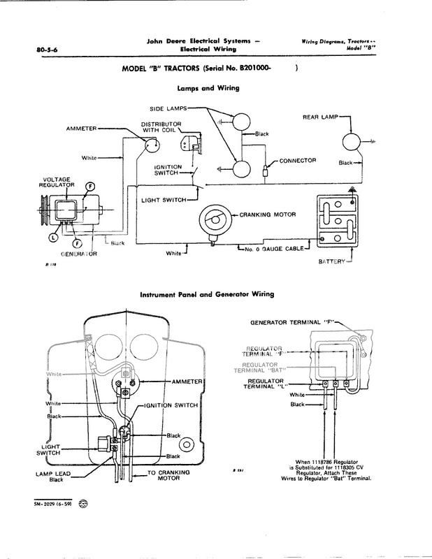
I am in the long process of restoring my 1947 early Model B John Deere. !947 was the upgrade year for the newer late Model B. My tractor fell in the middle of the production year and therefore is a combination of the both the early and late Model B tractor. Trying to restore this tractor has had it problems. My latest problem is re wiring the electrical system. So here is my problem. The generator is a three brush generator with an "A" (armature) and "F" ( field) posts. The new regulator has three post; "L" (load), "Bat" (battery), and "F" (field). The light switch has three posts for lights, battery and a resistor. My confusion is with the "L" on the regulator and the resistor on the light switch. With this configuration, can anyone help me out with the proper way to wiring the tractor? According to the parts manual all my part numbers are correct.
 
There were basically two different charging systems used (manual Low/High on light switch or Voltage Regulator) and on different years and models two different Voltage Regulators (3 or 4 terminal).

1) Manual light switch Low/High charge control that used a Cutout Relay instead of a Voltage Regulator. Gennys FLD wired to light switch

2) Automatic charge control that used a Voltage Regulator (NOT just cutout relay) and the light switch controlled the lights only not the charging.

3) Voltage Regulators used were 3 terminal
BAT GEN/ARM FLD in which case loads like
lights and Ignition were fed off the ammeter

4) Voltage Regulators used were 4 terminal
BAT FLD LOAD GEN/ARM in which case loads
like lights and ignition were fed off the
VR's 4th LOAD terminal instead of ammeter


A) If it uses a 3 terminal Voltage Regulator

BAT on VR to load side of ammeter
GEN/ARM on VR to Gennys ARM post
FLD on VR to gennys FLD post
THE GENNYS FLD DOES NOT WIRE TO LIGHT SWITCH

B) If it uses a 4 terminal Voltage Regulator

BAT on VR to load side of ammeter
GEN/ARM on VR to gennys ARM post
FLD on VR to Gennys FLD post
LOAD on VR to light/ignition switch
THE GENNYS FLD DOES NOT WIRE TO LIGHT SWITCH

c) Manual light switch Low/High and CutoutRelay

BAT on Cutout Relay to ammeter
GEN on Cutout Relay to Gennys ARM post
FLD on Genny up to Low/High Light switch

See Diagram for a 1947 B for a Light Switch Low/High manual charge control and cutout relay NOT a Voltage Regulator. Its possible to convert from a cutout relay and light switch to a VR as described above but in that case do not wire FLD to light switch but to VR instead.

John T
B-1-Jpeg.jpg
 
Thanks John T for your reply. I am still a little confused. The regulator that I have has three terminals- L (load), Bat (battery and F (field). You mentioned that the three terminal regulator wae Bat, Gen/Arm, and Fld. Do I need a different regulator?
 
Lon, if you look UNDERNEATH that VR I bet it has a GEN/ARM terminal. Many 4 terminal VR's are configured that way, BAT LOAD FLD on top side by side with GEN/ARM off on one side by itself or underneath. Here's a diagram for a later B with a 4 terminal VR. That one used a Wico XB Battery Powered Distributor Ignition however.

John T
B-3-Jpeg.jpg
 

We sell tractor parts! We have the parts you need to repair your tractor - the right parts. Our low prices and years of research make us your best choice when you need parts. Shop Online Today.

Back
Top