How do I convert a new Delco-Remy to 1 wire alternator?
This is for my Ford 850 conversion from 6 volt to 12 volt
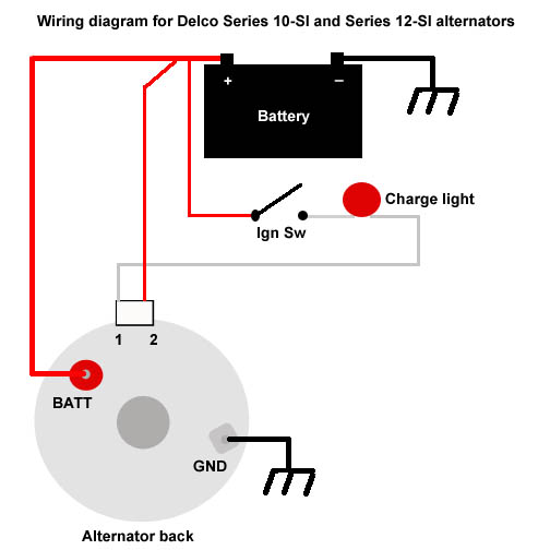
I connected a wire from spade post #2 to alternator Battery post to make a 1-wire alternator.
I ran a wire from alternator to battery post on 3 post solenoid where the battery thermal positive side is.
I ran a wire from solenoid battery post to off side of switch.
Tractor runs, but trying to figure if alternator is charging.
I have this light (idot) that is supposed to light up the 14.0 light if alternator is charging it does not.
Does this alternator have to run 3000 rpm to start charging and then the idot light will show alternator is charging. If so I do not have a gauge to tell when 3000 rpm is reached I guess this is full throttle I do not run full throttle with this tractor this could be a problem for me.
I tried the gauge on my Ford 601 workmaster and the gauge show the alternator is working in idle speed.
So I am pretty sure the gauge works.


This is for my Ford 850 conversion from 6 volt to 12 volt
I connected a wire from spade post #2 to alternator Battery post to make a 1-wire alternator.
I ran a wire from alternator to battery post on 3 post solenoid where the battery thermal positive side is.
I ran a wire from solenoid battery post to off side of switch.
Tractor runs, but trying to figure if alternator is charging.
I have this light (idot) that is supposed to light up the 14.0 light if alternator is charging it does not.
Does this alternator have to run 3000 rpm to start charging and then the idot light will show alternator is charging. If so I do not have a gauge to tell when 3000 rpm is reached I guess this is full throttle I do not run full throttle with this tractor this could be a problem for me.
I tried the gauge on my Ford 601 workmaster and the gauge show the alternator is working in idle speed.
So I am pretty sure the gauge works.