Small engine charging diode, what am I missing

Butch(OH)

Well-known Member
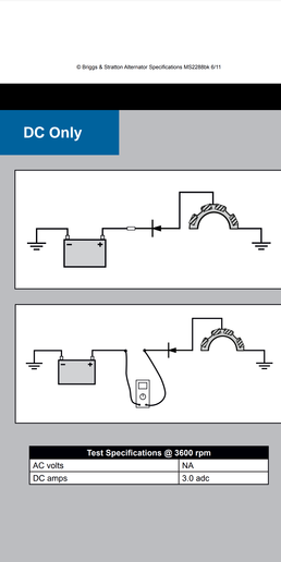
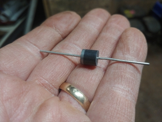
Sorry for the necessarily long question here but I am close to the lowest level when it come to modern electronic gizmos. I do manage to feel my way around old school charging and currently I have have two small engines in the shop that were not charging the batteries. These are not regulated two wire AC type but the old one wire sytem with a stator under the flywheel that produces 25 or so volts AC and a single wire with a diode in it going to the battery. The diode rectifies the AC currect and also cut voltage in half. Now on to my problems. Engine number 1 has a diode that reads shorted both directions. The B&S part is pretty spendy so I go online and find some diodes rated at 20 amps and like 1000 volts for a dollar each. I wired one in on engine 1,, yes it was installed the correct direction, yes the battery was new and charged. Start the engine up and check the voltage and it is just over 13 and coming up as it should with one of those 5? or less Amp systems. Fixed! but after 30 seconds it quit charging and the diode was so hot it burned my finger tip and when I shut the engine down it was shorted both directions. OK junk diode,, soldered in another and it did the same thing,, ok I bought junk diodes. Next try, it so happens that I keep several type 5010 bridge rectifiers in the shop because my ST type stand by generator uses them. They are rated at 50 amps. I just used the + and minus terminals and again it was installed the correct direction. As I understand a bridge rectifier I am using half the diodes in parallel, or half current each?? Well after a couple minutes running and charging correctly that bridge rectifier started smoking and it too is now shorted both directions. OK enough of that engine for now and I proceeded into engine number 2 which is powering an 8 KW gen set and has same problem which is battery not charging and wire that is supposed to charge the battery is producing 29 volts AC. Bad diode as I was taught in school. I get behind the panel and find that they used the same 5010 bridge rectifier only using the + and - terminals just like I tried on engine #1. It is obvious that it was that way from the factory and not a bodge by a previous owner. The rectifier was shorted both ways as I suspected so I wired in one of my spare 5010s and it charged for 15 minutes, got hot and same deal as before is now shorted both ways.

I am thinking there are other issues beside bad diodes. I hate to buy a $30 BS diode and have it do the same thing, they are tiny and shurly wont handle the current that my replacements will? Anyone care to take a stab at what's going on?? Appreciate it.
 
The solid state device is likely a Zener Diode Rectifier and voltage limiter device. They have a diode symbol with a mark through it. Red about them. Jim
cvphoto72897.png
 
And if it truly is a zener diode, you have to know exactly how they work because on a schematic it appears they are put in backwards.
 
Thanks for that, I did some looking at diagrams and manuals and thy all say it is an unregulated system using a diode and charging rate is 3-5 amps. Looked at a dozen diagrams and all show a regular diode as attached. The standard B&S diode is a tiny thing that looks uncapable of handling more than a few amps, any more thoughts?

cvphoto72920.png
 
Conventional Diodes have a PIV rating Peak inverse Voltage if it is exceeded by a pulse of higher voltage they become shorted and conduct both ways. This can lead to the battery discharging through them to ground (hot). The Fact that companies label them diodes doesn't mean they are not Zener Diodes. Jim
 
The diode is just a standard power diode. Absolutely not a zener diode. That would not make sense for this application. The diode show in the diagram is correctly oriented, the line should go to the positive terminal on the battery. If using a bridge rectifier then do not use the AC terminals, just use the two output, positive and negative, terminals. I know someone will post that 50% of all diodes are bad out of the box or some nonsense such as that but these diodes are old technology and rarely go bad. Without a diagram of how you hooked up the diode I can only guess but some possibilities are that the diode is hooked up backward, the line on the diode should be towards the battery, a short downstream from the diode, or the diode was damaged by soldering heat.

I would test the new diode prior to using it just to be sure, hook up the diode without soldering by using jumper wires and without the engine running. Check the current flow and it should be zero since the engine is not running. Not much is going to burn a 50 amp diode coming from a 3 amp alternator but a battery flowing backwards into the alternator will burn that 50 amp diode.

A picture or diagram would help sort out the problem. Briggs used several types of one wire stators, an engine model number would also help.
 
well, if it was in my shop, I would remove the flywheel and inspect the stator for any burn marks or shorted places.

Also, those diode systems were mainly for charging the battery only or battery and fuel solenoid. Is the machine the engine is on still pretty much stock? For instance, that diode system won't run an electric clutch.

A third thought: Those low amp charging systems used a flywheel with smaller magnets. Has the flywheel been changed for some reason?
 
Thank you I will check that out. They appear to be non-messed with prior to my fingers being in them.
 
Interesting. The diodes are definitely getting too much current, which makes no sense. The stators on those old, non-regulated charging systems are very limited in how much current they can source. Even if the battery was completely shorted, the stator shouldn't source enough current to burn up the diode. Is it possible someone installed a stator off a regulated charging system? Or maybe it needs a VR instead of a simple diode?

The most reasonable explanation is you've been installing the diodes backwards and are mistaken about the battery charging. There's simply no way that stator can source 50 amps. But the battery will have no problem at all doing so.
 
OK, So here is how I have been double checking my diode orientation. After installing the diodes I touch the battery cable back to the post and look for a spark. Shouldn't that detect if the diode was reversed? Also the systems both charged when first started up, would that also indicate correct installation?
I temporaried another 20 amp rated diode in the Briggs last night and same results as before. As you said, there is no way a 5 amp charge should be burning up 20 amp diodes

Very confused in Ohio,,,Grrrrr
 
Touching a diode to a source (especially a 100 amp source) can instantly cause damage. Testing it using a test light as an indicator is far and away best practice. If it lights, it is flowing if not it is blocked. Jim
 
> OK, So here is how I have been double checking my diode orientation. After installing the diodes I touch the battery cable back to the post and look for a spark. Shouldn't that detect if the diode was reversed?

Well, that's not how I would do it. You can damage a diode if its peak forward current is exceeded for even a few milliseconds. It's better to rely on the diode markings; the end marked with a ring is the cathode and is connected to the POSITIVE battery terminal. Or check with an ohmmeter.

> Also the systems both charged when first started up, would that also indicate correct installation?

You don't say how you determined it was charging. If you checked the battery voltage before starting, and it rose a volt or two after starting, then I'd say your diode was hooked up correctly.
 
Mark, I did check the markings and verified them with a meter. The wire touch was just a double check. Yes the system was working correctly when started up. If you have played with them they do not instantly bring the battery voltage back up but depending on the state of the battery it takes a several seconds to several minutes to achieve full voltage. The engine in question was at 12.5 volts before I started it and was at 13.1 and climbing a minute later when it stopped charging.

Going back to the shop to double-check everything involved. This is the diode I am using, rated 20 amp 45 volt

cvphoto72994.jpg
 
A diode can be damaged EITHER by exceeding its current capacity OR if a voltage that exceeds its PIV rating is applied. One has to be careful just applying a voltage source without any current limiting protection as excess current can damage it quickly.

John T Longgggggg retired n rusty EE so no warranty
 
I am assuming you have just ordinary rectifier diodes, not zener diodes, and you know how to install with the correct polarity and know how to use an ohm meter to test correctly. Since you did not get a spark when hooking to the battery then the diode should be the correct polarity and no down stream shorts.

You could have an intermittent short that overloads the diode when the engine starts to run and the wires vibrate but I would think the battery current would fry those same wires. Another possibility is the starting switch is sticking in the start position or the starter solenoid is sticking and keeping the starter engaged. That may be enough current draw from the battery and the charging system to burn a diode but not wiring since the battery to starter wiring is separate.
 

If battery voltage is rising, you've installed them in the right direction.

SO...either current or piv is exceeded...

You might measure the open voltage on the charge lead,,,, to ground and see what the ac voltage is... this will determine your piv... your diode needs to have a junction thick enough to keep the piv from punching a hole and shorting across it.

As a temp measure... find a tailight bulb and put is in series with the diode.. the size of the resistance in the bulb will help control the current and act as a regulator. this way the current will be controlled.. the battery will charge, but it will be slower... light bulb might even glow a bit if higher current, till it tapers off as the battery voltage come up and the current drops... Light bulbs have been used for years for albiet cheap voltage regulators in test circuits. you can actually tune the charge rate by selecting different bulbs ie an 1895 dash bulb will cut it to to milliamps. an 1157 bulb will normally draw .68 amps on the low filiment and 1.97 amps on the high lead... and if the bulb burns out, it acts as an fuse for your circuit for drawing too much current. Again a poor mans voltage regulator for testing and mock ups.... with a visable current meter... to tell you your getting close to max current...

wondering if your charge lead is next to the spark plug lead and picking 1000s of volts due to induction??
 
Inductive sources like the alternator in these may produce transient voltages exceeding 80 volts. That voltage might not appear on an analog meter, and be just wild on a cheap digital. It would disappear on a good digital that averaged a thousand samples. So an oscilloscope would see it. But way too much trouble. 200 volt PIV is where i would go. Jim
 
So Jim when was the last time you even saw an O Scope?? Or are you like me you own one?? I have a Navy surplus O Scope much like what I used when I was in the Navy
 
I read the original post, it makes no sense to me either.

I wouldn't think they would design something so minimally that a dead battery or short to ground would take it out.
Even if the output side of the diode were grounded I don't see the little coils under the flywheel making enough amperage to burn it up.

I tried to look up the difference in diodes and zener diodes. It is way beyond my understanding. Something about it passes current both ways... I call that a resistor, and that would discharge the battery!

Be interesting to know the final verdict!
 
One thing I've learned in many years of troubleshooting is this: If something doesn't make sense, you've overlooked something. Start from scratch and confirm all your previous assumptions. Is the battery installed correctly and is it CHARGED with the right polarity? Do you have a good ground reference when you're checking voltage?

There are only two common reasons for diode failures: excessive forward current or excessive reverse voltage. It's pretty difficult to exceed the diode's peak inverse voltage in that setup, so the most likely cause is excessive current. And there's only one thing on that machine that can source enough current to blow a 50 amp or even 20 amp diode, and that's the battery.
 
> I tried to look up the difference in diodes and zener diodes. It is way beyond my understanding. Something about it passes current both ways... I call that a resistor, and that would discharge the battery!

Steve, a zener diode is no different than any other diode, except its reverse breakdown voltage is precisely defined. If we take a typical general-purpose diode, say a 1N4001, it will have specified MINIMUM peak inverse voltage, 50 volts in the case of the 1N4001. But it's ACTUAL breakdown voltage could be anywhere from 51 volts to 200 volts or more. It would still meet the spec.

A zener diode, on the other hand, is specified by its actual breakdown voltage. A 1N4739A, for example, has a specified nominal breakdown voltage of 9.1 volts. And since a diode's breakdown voltage is stable over varying conditions, if you reverse-bias a zener diode with enough voltage for it to go into breakdown, it becomes a very stable voltage reference. And in most applications, zeners are used as references, not as actual voltage regulators. (A reverse-biased zener needs to dissipate a lot of heat, so it's usually preferable to keep the current through it to a minimum. Which precludes using it directly to regulate voltage.) Pretty much any solid-state voltage regulator will have a zener diode in it somewhere.

But all this talk of zener diodes is a red herring. These engines don't use zener diodes.
 
I hadn't seen one since back say 35 plus years ago till I found this one in a military surplus store. Picked it up for $20. Haven't tried to use it just figure it would be something to have
 
What about trying a diode from a Delco 10si type alternator? I don't know the specs, but they seem fairly heavy duty. I know they are not like the ones that Briggs used, but maybe worth a try?
Garry
 

We sell tractor parts! We have the parts you need to repair your tractor - the right parts. Our low prices and years of research make us your best choice when you need parts. Shop Online Today.

Back
Top