Voltage regulator

Stephen Newell

Well-known Member
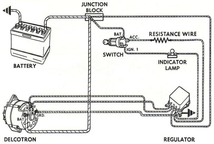
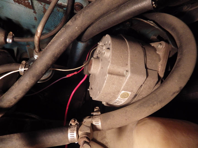
I'm trying to install a voltage regulator to my 1975 jeep cj5 where it's never had one. I went to NAPA and bought a VR142SB voltage regulator which is suppose to be just a universal external regulator. Of course the thing didn't have any instructions with it so I found some basic instructions online which I'm going by. Where I'm having trouble is the line which calls for a resistance wire. I went to two different auto parts stores this evening and nobody has any idea what resistance wire is, me included. Anyway since the jeep has a coil resister between the power and the coil is the resistance wire necessary? If so can someone recommend a suitable wire for this purpose. It looks like I may have to mail order the wire.
a164576.jpg
 
A couple points:

1 - Your Jeep came from the factory with a Delco 10SI INTERNALLY regulated alternator. Thus no separate external regulator.

2 - The wiring diagram in your post is for a Delco 10DN EXTERNALLY regulated alternator. This was used on vehicles made before about 1972.

If you are having voltage regulation problems recommend removing the alternator and getting it tested.
 
Others will say this also, but use the internally-regulated GM alternator. Find one for a '75-ish Chevy.
The next time you WON'T have to buy that expensive, made-overseas, POS external regulator, you'll thank us.
 
Not sure why you are wanting to do this, but...

The diagram you found is not exactly clear. You don't need the resistor wire AND the indicator light. It's an either or situation.

You can use an indicator lamp as a resistor, or a 35-500 ohm resistor, or even a diode.
10DN wiring
 
I'm not really sure what is the problem. I've had this jeep for almost 20 years and ever since I've had problems with gauges burning up. It's a terrible job replacing the gauges so since I'm putting new ones in again I thought I would try a voltage regulator. I even bought a wiring harness one time and rewired the entire jeep but still the gauges keep burning up. I've replaced the alternator three times. The last one was producing 16 volts. I do have an alternator which has an internal voltage regulator. It is off a 1986 Ford Tempo. It just has more wires to deal with than the regulator I bought at NAPA so I thought I would just go with the external regulator which only has 4.
 
I wouldn't put the alternator from the '86 Tempo on your Jeep. It probably wouldn't fit in there without modifications anyway.
Care to take a photo of the alternator in your engine compartment of what you have in there now and post it here?
I'm curious exactly what type of alternator that you currently have in there.
As posted before, your Jeep SHOULD have come with a GM internal regulator and that's what you really want to go back to, IMO.
While they never were the most reliable alternator on the market, they are about the cheapest to replace, very easy to troubleshoot, replacement parts were very common and seldom overcharged the battery.
 
Here is a nice article on testing gauges.
http://civilianjeep.info/Strenk/Gauge%20web%20page/basic_troubleshooting_for_cj_gau.htm
the failures are likely do the regulation resistors mentioned, not the alternator/regulator. I agree with the others, go back to an internally regulated alt. So much more reliable and easier to install.o
 
Here is the picture. I hope you can tell something from it. To me an alternator is an alternator.

Other than maybe electrical the alternator from the tempo would fit. The body of that alternator matches what is on their now.

This jeep hasn't had a voltage regulator of any type since I've had it and like I said there has been a complete wiring harness so there is no wiring there for a voltage regulator. Whether I use an internal or external regulator there will have to be wiring run for it.
a164593.jpg
 
That photo looks like a Delco 10SI with a steel fan. Plastic fan would make it a 12SI. It has a built-in voltage regulator and I see three wires going to it (like it should be). If the little two-wire plastic wire-plug goes in the top or side, it has a built-in regulator. If it plugs in the back, it needs an external regulator.
 
That 10DN in the photo would have a two-prong wire-harness plug that goes in the back of the alternator. If an SI series, the plug will be on top or the side and has a built-in regulator.

Regulators tend to be "Type A" or "Type B." Type A sends positive current to a brush like a Delco 10SI . Type B sends negative current to a brush like with a Delco CS130 and many Fords.

They all have regulators somewhere. Inside the alternator, outside the alternator, or just a chip in the main computer.
 
The two wires you see are two that I had done in the process of wiring the voltage regulator. On the alternator they are marked R and F. There is a white plug on the side of it.
 
In auto applications, "resistance wire" is usually a length of nickel-chromium wire used in place of a ballast resistor for the ignition coil. What it's doing in that diagram is beyond me, but I wouldn't trust it. The other guys are right, you should have already an internally-regulated alternator, adding another can't do any good. Your wiring harness should have a plug that fits the alternator; one wire should be hot all the time, as should the post terminal; the other one goes to the idiot light on the dash. 16V is way too high, but I doubt that's what's burning your gauges up. Try to find a wiring diagram for the Jeep.
 
I have the instructions for the wiring harness I put in several years ago but there isn't any reference to the alternator in the instructions. It was a Centech wiring harness. If the R and F on the alternator I have is the voltage regulator I just need to know where they are suppose to go then. Originally I think the F wire went directly to the cable off the battery and the R wire wasn't connected to anything.
 
I decided to repost the guage caution, more clearly, from my earlier post. When guages burn out, especially more than once, my first suspect would be high voltage from the instrument cluster voltage regulator, not the vehicle system voltage.

This is copied from a Jeep enthusiast web page and explains it more clearly than I:


This article only covers gauges and sending units used in the AMC Jeep CJs built from '72-'86, but some of this information will be useful for owners of other Jeeps. There are some slight variations with the Jeeps built from '72-'75, but starting in '76 things remain pretty consistent for 10 years.
About the Gauges

The meter movement in all the gauges have a built-in dampening mechanism which keeps the needle from bouncing around. The dampening mechanism is basically some thick grease on the movement's pivot points.

The reason all the meters are dampened is because the senders do not have a very constant resistance. If you put a good testing meter on the sender while the motor is running you will see the resistance bounce all over the place. The dampening averages out the reading. This also is why it takes a few seconds for the needles to come up to position instead of snapping to a reading.

When ordering replacement Fuel and Temp gauges for your Speedometer cluster, Stewart Warner brand are considered the best. These have "C" and "H" as well as the "E" and the "F" in the stock OEM orientation.

Imported after-market gauges have these ranges reversed, both are 12v, and have a different wiring and post setup. Use their instructions and diagrams during replacement.
About the Sending Units

The oil pressure sender is similar to the fuel gauge sender. The mechanical parts are different, but after that it is basically a coil of resistance wire wrapped around a card and the wiper moves across the winding to change the resistance. The higher the fuel level or engine oil pressure, the lower the resistance. With less resistance, more current flows and the gauge reads higher.

The oil pressure sender and fuel sender are both electro-mechanical devices but the temperature sender is not. The temperature sender is a temperature dependent resistor (Thermistor). The type in the Jeep is a NTC (Negative Temperature Coefficient) which means that as the temperature goes up, the resistance goes down.
Gauge Sizes
Gauge Diameter
Oil Pressure 2"
Volt meter 2"
Tachometer 2-7/16"
Clock 2-5/8"
Speedometer cluster 5-5/8"
Fuel and Temperature Gauges

Back of speedometer, fuel, and temp gauge

From the passenger side which is left to right in the picture above.

Fuel Gauge S Terminal - pink wire (from fuel sender)
Fuel Gauge A Terminal - 12v side of Jumper/Regulator Strip to temperature gauge
Fuel Gauge I Terminal - red wire (ignition-on hot 12v)
Temperature Gauge A Terminal - Jumper from fuel gauge A terminal (Jumper Strap regulated to 5v)
Temperature Gauge S Terminal - Purple wire (from temperature sender)

Some manuals have the positions of these terminals incorrectly identified. You can see the letters stamped in the insulation material around the posts.

The Jumper/Regulator Strap is composed of two strips of metal that continuously make and break contact, regulating the output to the Temp gauge to 5 volts. A volt meter applied to the A terminal on the Temp gauge should fluctuate (plus and minus) near 5 volts. A reading of 12 volts on the temperature side indicates a bad Jumper/Regulator Strap. 12 volts applied to the temperature gauge's A terminal will cook the gauge.

No matter what you decide to do with the alternator, be sure to check the cluster voltage/wiring. Just want to be sure another gauge failure doesn't happen.
 
In my jeep there is just power going from the electrical system to the fuse box where it's distributed where needed. There is no instrument cluster voltage regulator. This is the reason I feel like I need a voltage regulator.

The oil pressure gauge I have is the only one there is no problem with. It has a tube which carries oil from the engine to the gauge which operates it.

I should have the correct wires going to the fuel gauge and temperature gauge. The wires in the wiring harness is marked which one is which. Visually looking at the speedometer from the drivers seat the temperature gauge is on the left and the fuel gauge is on the right.
 
I did find the model number of the alternator I have. It's a duralast DL7127-9M. I can't find any specifications at autozone which say if it has a voltage regulator or not.
 
It is a 3 wire internally regulated alternator. Fits many GM AMC and others .
Poke around Autozone and it will tell you.
 
Ok, now I looked for a wiring diagram and couldn't find one specific to that alternator. I then looked up "How to wire an alternator" and got a bunch of different ways so really I'm back to square one. Most of them just show the wire from the R terminal being just for an idiot light which I don't need. I don't see how the thing can regulate the voltage if the power doesn't pass through the regulator and then to the gauges.
 
I would look for a wiring diagram for your jeep and try to find the wire color codes. You must have original wires hiding someplace . Does this white plug you mentioned cover two spade terminals? I did find on the INTERNET the part number of alternator you mentioned could be a "one wire" alternator.
I also found it was not a "one wire " alternator.
 
The alternator has two spades on the side of it. One is marked R or 1 and the other is marked F or 2. The way it has been used is the red wire F went to the positive side of the battery. The white wire R was just taped and not used.

There won't be any old wiring hiding in the jeep. Every single wire in the jeep has been removed and replaced with new wire which was prewired to a new fuse box. I do still have the instructions to the new wiring but the alternator is not illustrated. There is text saying to run the red wire to the incoming wire to the battery and wire the white wire to an indicator light. Since I had no want of an indicator light I just taped it.
 
(quoted from post at 23:46:48 07/02/17) Ok, now I looked for a wiring diagram and couldn't find one specific to that alternator. I then looked up "How to wire an alternator" and got a bunch of different ways so really I'm back to square one. Most of them just show the wire from the R terminal being just for an idiot light which I don't need. I don't see how the thing can regulate the voltage if the power doesn't pass through the regulator and then to the gauges.
he AZ number that you found with the 7127 digits is definitely an internal regulator Delco 10-SI. R=1 and F=2 in this diagram. The idiot light may be a resistor (discrete or in the harness resistance wire), or even a diode.
 
Take a look at the link in my first post, or just google 75 jeep instrument voltage regulator. Lots of diagrams/info out there. Most older cars/trucks used some method to lower voltage to the cluster.

I think yours should be in the fuel gauge, but some are separate.. Just a simple on/off bimetal type.

Maybe yours is different, but it would be a rarity.
 
R1 is excite wire and should be wired to indicator light or to Accessory terminal on 4 position ignition switch. I would un tape your white wire and hook it to R1 .
R2 is remote sense and can be hooked right to the battery + on back on alternator.
If you have lights and heater a better place to hook it would be closer to Bat + at the battery or follow the battery + cable at the battery to the first place it connects to solenoid , junction block etc. This is a better place to sense voltage needs. Sensing voltage needs at the alternator does not get optimum performance from your alternator.
 
The resister wire is in the circuit to lower the current that backfeeds into ignition switch from a running alternator. If that resister/lite/diode is not in that circuit the ignition switch would receive power from that wire and you wouldn't be able to turn the engine off. This is only true though if the resistor wire is hooked to the ignition terminal on the ignition switch.

We always hooked the resisted wire/exciter wire to the accessory terminal as in the picture above. This way the resister wire gets power during engine cranking and excites the alternator but after the ignition switch rolls back to the run position the accessory terminal is dead (isolated) from all other circuits inside the ignition switch. Then there is no back feed from the alternator thru the ignition switch to the ignition circuit. There is no need for a resistor of any kind if hooked up this way since the ignition switch is actually opening the circuit after starting. Our shop has wired many many of these with no problems or comebacks. Some may argue this point. But a diode stops all back feed, an idiot light is a resistor that doesn't allow enough current to backfeed for what the ignition system needs to function.
 
Stephen if your jeep is a 1975 I'm sure it has an instrument voltage regulator. It will most likely look like a 12 volt circuit breaker about 1" long, 1/2" wide with 2 termnals and possibly a small mounting bracket. It's not going to look like a conventional charging system VR.
 
I believe I have seen those ICVR functions built into the gauge cluster, but don't know how a person would know???
 
There is nothing like that in the jeep. The gauges are two individual units installed inside the speedometer. I also have taken the gauges apart and there is nothing inside the gauges.
a164784.jpg

a164785.jpg
 
Thankyou, I think that is enough information I can finish the project for the voltage regulator. I will remove the external regulator and wire the internal one as illustrated. I think I will get a gauge cluster regulator before I power up the jeep again though.
 
No, no such critter. It may have been born with one but hasn't had one since I've owned the jeep. Then some time back I had trouble with the fuse box and installed a complete wiring harness with a new fuse box. Everything electrical on the jeep now is what I installed.
 
If you are using factory gauges, the lack of a regulator will cause them to fail as they are designed to run on less that 12v.

If aftermarket, all bets are off.

What did you decide on the alternator: using externally regulated or internal?
 
I plan to correct the wiring and use the internal regulator on the alternator. Then get a instrument regulator to put between the power from the fuse box and the gauges.

I figured the voltage was reason I was burning gauges. What's puzzling though is this last time the voltmeter burned up also and it goes up to 18 volts although I've never seen it register more than 14.2 volts.
 

We sell tractor parts! We have the parts you need to repair your tractor - the right parts. Our low prices and years of research make us your best choice when you need parts. Shop Online Today.

Back
Top