Help wiring this old Hobart!!!

therrera

New User
Hello people,

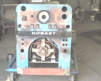
I am stuck with putting this Hobart back into service. I rescued it from the scrap pile and am almost there but I need some better minds than mine.

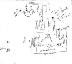
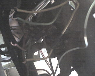
This welder was missing the local/remote toggle switch and also the name plate that contains the specs for it. I found 4 cut wires behind the panel where the switch was with no clue as to how to terminate them. The 4 wires are color coded two yellow, red and green. The two yellow ones go to the panel rheostat and the remote plug respectively. The red one goes to the second commutator from the front and the green one goes to the first commutator from the front. I tried all combinations I could think of to see if it had any effect on the power output of the welder, it didn"t. I think it needs to be flashed, but do not want to do this until I have the wiring connected properly.

I ordered a manual for a G-3010 but the wiring diagram is different and instead of 4 wires to the local/remote switch, it shows six. Plus my engine is a Willy"s flat head 4 cylinder, the G-3010"s I"ve seen pictures of have a Chrysler six slant six. Makes me think that either mine is NOT a G-3010 or my version is earlier than when the ones I"ve seen pictures of.

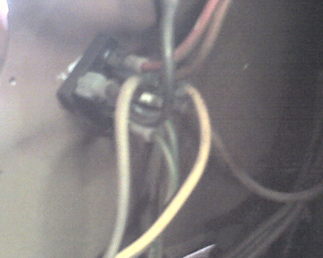
I traced each of the 4 wires and drew a diagram so that others might be familiar with what I am facing and know how to deal with these wires. I have tried to test weld with it but so far it refuses to generate welding power (or ac power to the outlets). I don"t know if this is because it needs to have the local/remote wires terminated properly in order to complete a circuit or because it may need to be "flashed" (or both). I was gong to "flash" the generator according to instructions in the manual I ordered when I discovered that 4 of the 8 brushes were not connected to the wiring, the pigtails had fallen out of the brushes. I ordered new brushes all around and installed them yesterday. This where I am at now. The drawing shows one connection where the green and white wire terminates at a junction with 7 other wires. I don"t know what this part is called but there is a picture of this included that might help figure this out.

The engine runs fine, the welder does not weld. Also the AC ammeters, voltmeters are not working and appear damaged. I am looking for a source for these, but this should not prevent the welder from welding, only showing the power readings.

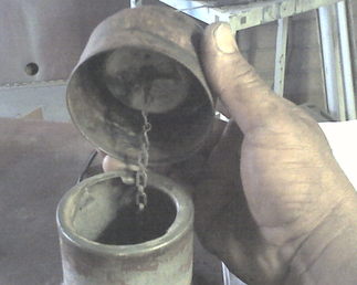
While I"m at it I need to find a gas cap for it as all it has is a home made cap that sits on the gas filler neck. Does anyone know by looking at the pictures?

Any help will be greatly appreciated.

Tony
a2331.jpg

a2332.jpg

a2334.jpg

a2335.jpg

a2336.jpg

a2337.jpg
 
Just connect the field wiring in series with a single pole toggle switch to provide a shut off. Your diagram has the info well laid out.Yellow from the "plug" to the red from com #2.Yellow from the rheostat to a new switch and then to the green. Of course the "remote plug" has to have a jumper plug across it to close the circuit.
You should be able to use a 12V battery and energize the excitation circuit without the engine running.Best place would be to remove the shorting plug from the "remote" plug then apply + to one side and - to the other of the plug. There should be current flow. If not the rheostat or brushes/comms are grungy. Or there is an open winding in the rotor.
The eight wires going to the block almost make the block look like an AC to DC rectifier but without more data ?????? I would be surprised a welder of that era would have an electronic rectifier.
The AC volt meters should be tested on AC to ensure they are not shorted.
The AC ammeters, would be the 1st time a shunt was burned open. Perhaps a jumper rigged to feed power through the ammeter and through the gen's main winding. With an old extension cored from a wall receptacle. Then power up a grinder or something. If the grinder doesn't start then the ammeter or comm/armature is open.
Ive seen circuits read ok with a multimeter but...........when actually loaded with normal running current and voltages. The strange stuff happens.
 
I think I see what your saying. Stepping back a moment and trying to understand the drawing (as opposed to just drawing it), I see the circuit that the switch would close.

The remote plug is where these machines would have a portable rheostat plugged in (via a six way plug in my welder, so that the amperage could be controlled from a distance. The switch would direct the circuit either to the panel rheostat of the remote rheostat.

I did not draw in all the wires in the remote plug as each contact has at least one wire (or jumper) going to it. I was concentrating on documenting where these cut wires went so it would not complicate my presenting the info.

The circuit drawn, as you propose, then would close with the addition of a jumper across the gray and yellow wires at the plug (and the switch). Right?

While this would probably disable the remote plug functionally, it then should get the machine up and running. Right?

If and when I got a hold of the correct wiring schematic, I could rewire it so that the remote plug (and switch) toggled between the two. I actually have a remote control that I intended to put on it, but again without a wiring diagram I have to put that on hold. It is not a Hobart remote, its a Miller that uses a three plug connection instead of six.

Thanks for your help. I will keep you posted.

Tony
 
Did you finally get a manual? I found mine in PDF on the shop computer and posted on the Hobart board for you to e-mail me and I would sent it.
 
Well, good news and bad news. The good news is that in speaking with some welder repair techs while looking for some replacement gauges today revealed that I didn"t need the gauges in order to make the machine operational. They are strictly informational. They suggested I simply disconnect them and tape the leads so they won"t short against anything.

This simplified my approach because up until then I was going on the assumption that these gauges played a role in completing the circuits and thus needed to be working.

The bad news is that I closed the circuit as you described (and the repair techs also confirmed your plan) with no results. The techs said that this particular model was "self-exciting" therefore not requiring jumping one of the rings with dc voltage to get the magnetism started. In looking at the manual for the G-3010, it makes no reference in flashing the generator whereas another manual for a different Hobart does.

I am not getting AC power to the 110 volt plugs either. This model has separate rings for the welding, the AC power and the self exciting circuit. Therefore, theoretically even though I may not be getting AC welding current, I still should be getting AC power to the 110volt plugs.

This is indeed a setback as the implication is that there is a problem at a more basic level (such as a shorted armature or broken winding, etc.)

Is there any information available on troubleshooting this type of equipment. I was able to get a small spark (like the kind you might get with some flashlight batteries) on the ac welding output connectors, . When I put voltmeter to it I got a 1 volt measurement of AC power coming from those connectors and .4 volts on the DC side.

I have and know how to use a volt-ohm meter, I just don"t know the things to test and how to test them.

I remember when I was just starting on this project when speaking to a welder repair tech about it, he said that if I got AC power to the plugs, then it meant that the generator was basically sound. The DC welding current came from a rectifier and that it narrowed down the possible sources of problem.

Would you know where I begin trying to isolate the problem? If I had to take it to a repair center I know it would cost me an arm and a leg and I doubt I would be able to afford it.

Thanks for any help,

Tony
 
All is not lost. I've seen machines with a wee bit of life fail to self excite and take off. We swapped the polarity of the field windings and away she went. I won't bore you with the details.
You could flash the fields with the 120 wall receptacle, an extension cords and two 120V lamps in series to handle 240V. And back feed power into the welders 120V plug.
The lamps will limit current and prevent the electricity from leaking out of the wires. Electricity looks and smells a lot like smoke.
Unless tested we don't know if there is an open circuit in the excitation, welding and/or 120vac circuits. Difficult to explain on the net but would only take a couple of minutes to perform in person.
A knowledgeable shop can re-wind an armature for a "price". It all depends on what it's worth to you.
I don't know but what are the chances of finding a "welder end" and bolting it to the existing motor & frame? Or getting an e-bay ST 120/240V generator and connecting it to the engine.
Then take the 120/240 and run an ordinary welder. Plus she would make a backup power supply capable of running a house without Micky Mousing around.
 
I forgot to mention.You can isolate voltmeters and everything will usually operate. Isolate and tape over the leads of an ammeter, she isn't going to work at all.
 
Thanks for your words of inspiration. I am not out of the fight yet. When I was a kid I used to build slot cars from scratch and in doing so had to learn the basics of electric motors and their inner workings. I remember testing armatures for shorts by putting a lead on one of the segments of an armature and then touching the iron core, one by one to isolate the bad winding. When found, I would rewind that pole.

I don"t suppose to rewind the armature myself, but I could maybe isolate any bad parts at that level to try and determine where the problem lay. It could be something as simple as a broken wire that is not completing a circuit or is burnt and only passing current by a few strands. I just need to know how to test the stuff and the specs they must match.

I will go on the net to search for material on that subject in particular and see what I come up with.

Would you suggest the wall outlet trick with this generator? It doesn"t matter if the current is AC? The flashing instructions I"ve seen for other models refer to using a 9 or 12 volt DC battery (flashlight batteries at that).

Is it possible to put a voltmeter to the slip rings (this one doesn"t use an armature)that power the AC plugs for example? Would it show power straight off the brushes?

What do you think?


Thanks again,

Tony
 
What is connected to the 3 & 4 brushes?
Where do the welding leads connect to the generator's wiring? Where does the 120V receptacle pickup it's supply?
That "exciter" circuit for controlling welding power has to pickup a supply from somewhere as well.
Some of these may be supplied from a separate set of windings on the armature?
 
Hi,

each ring actually has a pair of brushes, eight in total. I haven"t traced where each lead goes, but I can and get back to you. It looks like several of the brush"s pigtails are screwed into ground on the frame.

The wiring diagram I have for this model does not match the version I have so it has not been much help as there is circuitry shown that is not on my welder.

From the description in the manual on how this welder operates it says:

"The welding and power generator are on the same shaft with separate stators and housing. This gives complete electrical isolation of the two units. The AC power generator stator is towards the engine, and provides AC excitation for both generators and power to 115-V and 230-V AC receptacles for external loads, such as power tools, lights, etc. Both the power and welding generators are revolving field type. The welding generator is located toward the rear panel and supplies AC current for AC and DC welding. AC and DC welding current control is attained through the use of a tapped AC reactor. In the case of DC welding, this current is rectified and a smoothing reactor provides smooth DC welding."

I somehow twisted my knee and can hardly walk today. As soon as I am able, I will track down where each of the leads go that come from the different stators.

Thanks for the help,

Tony
 
Could you rib a test lamp with a pig-tail and a 120V 100W lamp? Then test for continuity across brushes 1-2,3-4,across the stationary stator winding(s) and through the welding current control/rheostat/remote plug circuit?
I would have to see those grounded brushes, usually the rotor is isolated from chassis?
 
Hi again,


I am not sure how to rig such a test lamp. I would have to have the neutral wire grounded to the frame and the hot wire going to the test lead/light, no?

I would be afraid of shocking myself in the attempt, unless I have it all wrong.

Couldn"t I accomplish the same thing using a 12 car battery and a test lamp? I would ground the armature and then test each brush one by one for continuity and / or short there.

Are you referring to doing this with the generator running and testing for 110v current? While I"m on the subject, can I put a meter on the brushes and see if power is being generated "raw" straight from the stators?

To check for continuity across the stators and the windings, the engine would have to be still. So are we talking about testing with the engine both on and off?

How would I test the rheostat for continuity? Would I ground one end and see if the test lamp lights up when touching the other end? Since I"m testing continuity not resistance, that should do it, right?

Also, those brushes that are grounded. I am assuming this is the case as they were missing the pigtails and there were no leads going to it. There are two of them. I will double check to see if they are insulated against grounding and it just may appear to be grounded at casual glance.

I am putting two and two together here. I remember looking at the wiring diagram for this welder (not the exact same spec number, just model number) and it shows six wires going to the local/remote switch (which is missing). I found only four cut loose wires where the switch was.

Could it be that the missing leads on those two brushes in fact go to that switch as well? This would certainly solve the problem of the discrepancy between what my welder has (four loose wires and no switch) and what the diagram shows. I will scan that page and send you a copy, maybe you can make sense of these clues.

Sorry to sound somewhat dense on this subject, I don"t have much experience in troubleshooting electrical problems except in the most simple of cases.

Thanks,

Tony
 
Part of this is terminology. People use the AC term "ground" for the chassis of DC vehicles and tractor's etc when it's not grounded. There is no connection to a ground rod in the earth. It's using the metal chassis as a return path.
Now getting into AC equipment. There are the live lines, neutral and ground. Several of us have tried to explain on this board for years that ground and neutral is not the same thing.
Needless to say people keep telling us ground and neutral is the same. Yet they have no answer of why we run two lines, a neutral and a ground to a stove or clothes dryer. Or why the U-Ground receptacle in the wall has the wires. A line, neutral and separate ground.
A 12V supply and a heavy load such as a car headlight will safely test for intact current paths.
This machine sounds like there is an "open" somewhere. Those disconnected AC meters if there are ammeters will stop everything cold.
 
Sorry for the misuse of the terminology. I was trying to figure out how do I connect my leads? Can I use a DC probe.

Should I attempt to "flash" this generator and how do I identify the connection were the power goes?

I haven"t tried to do this as I was first eliminating all the obvious (loose wires, missing brushes, etc.).

The wiring diagram I have does not seem much help as it is not specific to my machine only to the model no.

When I referred to "ground" I was referring to using the chassis as a return path exactly as you stated. So for testing shorts, should I proceed simply to test commutator (stator rings) to armature as see if there is a short? And between brushes too?

I went to the emergency room today to have my knee looked at. It is a torn cartilage. I will have to wait until I can walk halfway decent to pick this up again, probably in a week or so. I have a friend who can help me to do the checking.

I located a source for those ammeters on Ebay and can order them. One of them was bad for sure and if not shorted, had a broken circuit as its windings were all frayed and pulled out of place. I took them out and taped up the ends because two welding repair techs told me that they were strictly cosmetic and didn't interfere with the welding current.

I will replace the gauges. They will take about a week to get to me and in the meantime I can check for shorts and open circuits. I am open to the fact that they may be mistaken and it won't be the first time I find errors tech support advice.


Would you recommend as I described for starters?


Thanks,

Tony
 
I feel your pain. I've ripped a knee, ankle and a shoulder. Surgery on all three. Don't try to a hero and push the injury too far. You will just make it worse.
As you have stated. Continuity is everything, if the circuit doesn't ring through and carry current. She will never work.
Of course a short from a winding to winding or from a winding/wire to chassis will shut everything down.
 

We sell tractor parts! We have the parts you need to repair your tractor - the right parts. Our low prices and years of research make us your best choice when you need parts. Shop Online Today.

Back
Top