24v charging system

I have a cat d4d with a 3304 engine that I am trying to convert from a generator to an alternator. It has two 12 volt batteries connected for 24 volts for a negative ground system. I just got a new one wire 24 volt alternator and have gotten it mounted. How do I connect the new alternator correctly to ensure that both batteries are being charged? Also I am wanting to put a voltmeter in place of the old ammeter. Can anyone tell me the best way to wire all this up?
 
IF, the two 12v batteries are connected head-to-tail (just like the 2 D-cells in your flashlight), with no connection between the two batteries other than to each other, then you connect alternator output to the battery + (the battery that does NOT have its Neg post to ground. Voltmeter + to that same battery post and the voltmeter neg to ground. If you do this voltmeter connection without a switch (could use ign key sw if you have one?) then the meter will place a small drain on batteries 24 hours a day, 7 days a week. This could eventually matter, especially if there are days or weeks of non-use.
 
IF, the two 12v batteries are connected head-to-tail (just like the 2 D-cells in your flashlight), with no connection between the two batteries other than to each other, then you connect alternator output to the battery + (the battery that does NOT have its Neg post to ground. Voltmeter + to that same battery post and the voltmeter neg to ground. If you do this voltmeter connection without a switch (could use ign key sw if you have one?) then the meter will place a small drain on batteries 24 hours a day, 7 days a week. This could eventually matter, especially if there are days or weeks of non-use.
 
Simply connect the alternator output to the hot (battery) post on the starter solenoid.

OR.......connect alt output to the + battery post clamp for the UNGROUNDED battery.

----

To wire the voltmeter there are several options:

1 - Connect the meter + post to a switched terminal on the ignition switch (it is usually labeled IGN or ACC).

2 - If your machine has electric gages connect the meter + to the hot post on any gage or the hour meter.

3 - If the engine has an electric fuel shutoff connect the meter + to the fuel shutoff power terminal.

Connect the voltmeter "-" post to any convenient ground.
 
If its a 24 volt alternator and you have two 12 volt batteries wired in series.....The alternator needs to charge the series sum of 24 volts, and thats present from the + (outer untied post) of one batery to the - (outer untied post) of the other. The "tied" being where the two are wired together (+ to -) in the middle.

The alternator is configured for a certain case frame polarity I take it. It needs matched to the Cats polarity and you stated negative ground......

Likewise the voltmeter needs to be across the batteries series sum like above and should be switched on or off (via some existing switched location if at all possible) so as to not be a drain when not in use.

Best wishes

John T
 
my cat 24v 3304 has a master switch on the negative ground wire so the whole system is off when the switch is off.
 
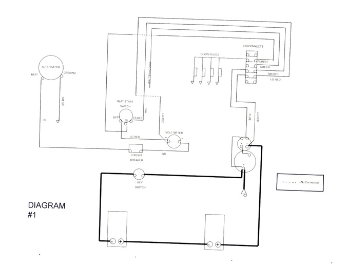
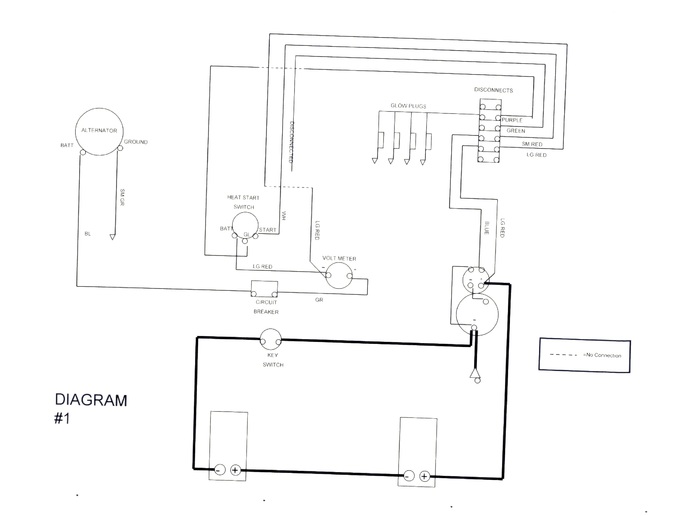
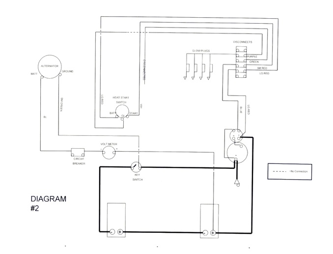
Thanks everybody for the replies. When I posted this I should have posted a diagram as for me to better understand the answers. I am putting up two different diagrams of how I have wired it so far and neither have resulted in the voltmeter working. I however did have around 13 volts or more on each battery with the dozer running when I check with my multimeter. And yes the alternator is a one wire negative polarity 24 volt.
a114904.jpg

a114905.jpg

a114906.jpg
 
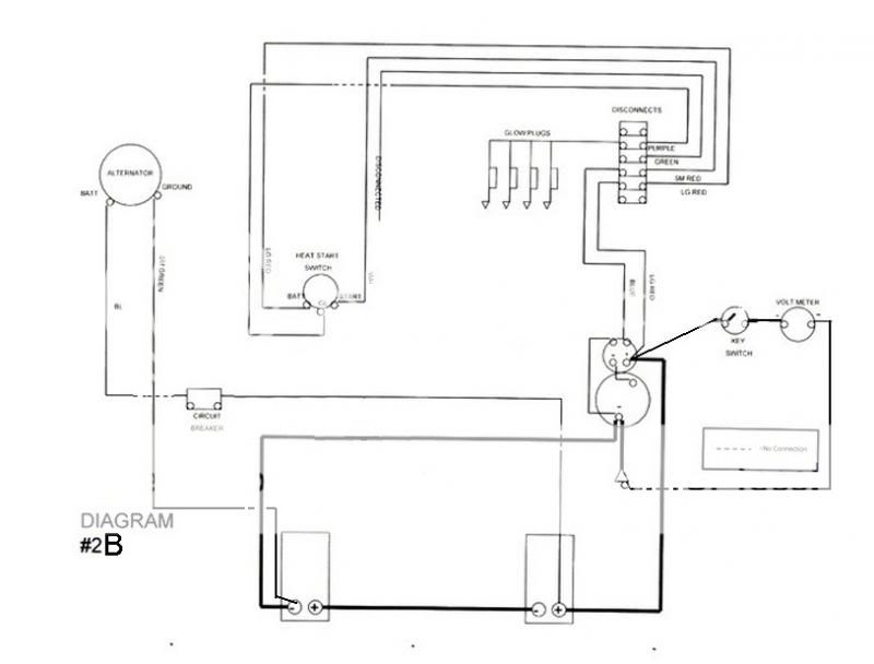
Looking at dwg#2 &/or #1, the way you have it drawn, it looks like 'key switch' is switching battery ground. I fully expect that it is not wired this way. In either diagram, it can't possibly charge the battery with the voltmeter wired as shown (maybe you have ammeter?).
Here is a potential diagram:
 
I can't see the diagrams well enough to be sure, but it looks like you are trying to hook it up with the power going through it like you would an amp meter. You can check out the linkbelow to either the Faria, or VDO guage sites if you want. Both say the same thing, but the VDO site has a simple diagram. Either way, here's the gist of what both say.

Too hook up a volt meter to read as accurately as possible, you need to hook the positive post to a switched wire as close to the switch as possible. The negative post on the guage then goes to a good ground. In essence the guage acts just like a test light, etc would be showing the voltage in the system to ground. Think about a test light, if the bulb glows weakly, the voltage is low, if it glows bright the voltage is good. Same goes for the voltmeter, higher voltage it shows higher on the guage, lower voltage it shows lower on the guage.

Beyond that, the wiring will be the same as any other wiring system in that the hot wire from the alternator will typically hook up to either the battery directly, or to another post connected to the battery such as the one on the starter, etc.

Hope this helps.
Faria voltmeter instructions

VDO instructions
 

We sell tractor parts! We have the parts you need to repair your tractor - the right parts. Our low prices and years of research make us your best choice when you need parts. Shop Online Today.

Back
Top