(quoted from post at 20:36:36 03/08/10)
(quoted from post at 16:42:58 03/08/10)
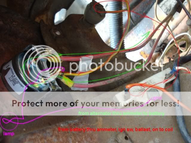
(quoted from post at 19:37:06 03/08/10) You must have missed the post. Originally the red wire and the yellow wire were on the outside post of the gauge. I tried switching those two to the inside post as you see now. That doesn't work either.
I "tape flagged" the one red wire so I wouldn't get the two mixed up.
Yes, I saw that. But you will notice that I spoke of swapping the two reds........not moving the yellow. At any rate, do the lamp connections I spoke of as they will give us information to work from.
I don't think you understand, originally the red (flagged) wire was on the inside post and the other red and the yellow were on the outside post.
In the picture of the gauge you see the wires after I switched them when I installed the new gauge and it did not work.
I wired a tail light bulb as you suggested. When I touched the flagged wire post the light lit and the amp gauge moved maybe a little less than a sixteenth toward the plus side.
When I touched the other post the lamp also lit but the gauge did nothing at all. Should both of those gauge posts be able to light the test bulb like that?
So, since gauge did move a little toward the plus side, I'm thinking I should switch the red and yellow back to the outside post and the flagged red back to the inside post and the test bulb should make the gauge read a little to the minus side.
But that is how it was originally wired and the old gauge and the new gauge did not work. So, I'm stumped.