Oil Gallery Diagram

RichMac

New User
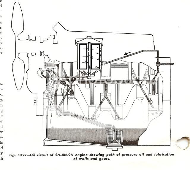
I have been unable to find a diagram of the complete oil gallery for the N series. Does anyone have one?
 
(quoted from post at 00:45:12 07/07/09) I have been unable to find a diagram of the complete oil gallery for the N series. Does anyone have one?
ill this show you what you want? Oil flows out of mains to rods, so the manual dwg has that wrong, but I put arrows on dwg showing correct flow.
oil_ckts_filter.jpg
 
After looking at the diagram, it seems that you are right. Most
engines have the oil flowing thru the crank and into the rods
which sprays onto the bottom of the pistons to cool them.

I was interested where the oil gauge is in the flow. It looks like
it is at the very end of the oil path thru the crank. If so, the
pressure has dropped many times before getting to the gauge. I
suspect that on these tractors a more important thing than
gauge pressure is oil flow even at low pressure. People who
measure low pressure may still have a lot of oil flowing thru the
rest of the noncritical parts of the system. This looks kind of
like a splash system with a pressure system added on for the
main bearings.

Does this make sense to you?
 
"I was interested where the oil gauge is in the flow. It looks like
it is at the very end of the oil path thru the crank. If so, the
pressure has dropped many times before getting to the gauge. I
suspect that on these tractors a more important thing than
gauge pressure is oil flow even at low pressure. People who
measure low pressure may still have a lot of oil flowing thru the
rest of the noncritical parts of the system. This looks kind of
like a splash system with a pressure system added on for the
main bearings."

Actually, the oil gauge is tapped into the back of the oil gallery, a steel tube put in place before the block was cast. It is simply a tube... the oil pump feeds the front, the oil channels to the main bearings are "tee'd" off of it, and the gauge port is at it's far end.
 
"Most engines have the oil flowing thru the crank and into the rods
which sprays onto the bottom of the pistons to cool them. "
That is exactly what is happening here in the N engine. Bob, explained path from pump to mains to gauge. Drilled in crank are paths from mains to rods and thru rods to wrist pins & spray holes to spray onto pistons. I wouldn't characterize as 'splash system', even though there is a bit of that on other parts not included in this discussion. As an aside, note also, that it is a partial or bypass filter arrangement, not the full flow filter of a modern engine.
 
In the diagram, the N's lube oil circuit appears to me to be lubing the cylinder walls. Are you sure the piston crown is oil spray cooled?
I wasn't aware that these older engines used piston crown cooling with oil spray. That's usually reserved for diesels or more modern highcompression ratio spark ignition engines with their higher gas temperatures.
 
You be right Jerry, as the oil holes are in the big end of rod , not small end.. Get enough eyes involved and the correct stuff will surface.
Thanks.
 

We sell tractor parts! We have the parts you need to repair your tractor - the right parts. Our low prices and years of research make us your best choice when you need parts. Shop Online Today.

Back
Top