Jeff_G

Member
Serial number 452659, should be a 1952 but this tractor has a front dist and the conduit on the head for the plug wires. Doesn't make sense to me. Also has a 3 wire alternator and external ballast resistor.
Naturally my service manual doesn't have a proper wiring diagram. Anyone have one or a link with this set up?
 
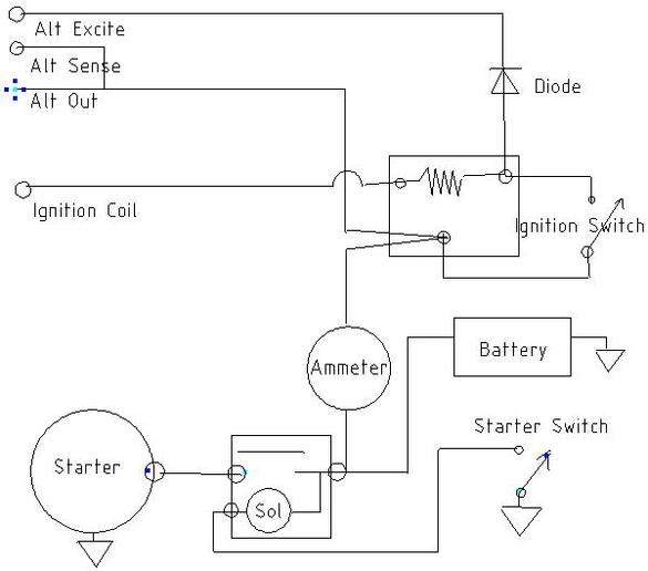
I would use JMOR's diagram for the earlier model 8N or 9N/2N.

mvphoto43716.jpg


mvphoto43717.jpg
 
" 3 wire alternator and external ballast resistor."

Pay attention to JMOR's notation about the resistor.

If it is a 12v coil, all you need is the oem ballast resistor ( see tip # 30)

Like at the bell housing behind the starter. It's probably says 8NB below the casting code, meaning that you have a sidemount block retro-fitted as frontmount.
75 Tips
 

I need to look at the tractor tomorrow. Not sure if there is a resistor block. It does have the push button neutral start switch as in the drawing.
 
If it were originally a side mount, it wouldn't have had the resistor.
There would have been a terminal block mounted in that location.
You can add the resistor in place of the block though.
 
I also have a front mount distributor, and it sort of gets a little mental adjusting to get used
to. Specifically, you cannot twist it to adjust the timing. The initial timing is set with the
distributor out, by moving the inner distributor plate. Next, the point gap is very small, .015",
and my tractor seems very sensitive to this setting. And there is no coil wire. On my 2n with a
front mount, once properly timed and properly set up, it's good for a long, long time.
 
Huh???? No coil wire??? It ain't gonna run then with no wire. The front mount distributors are not difficult to do - get out your essential manuals and follow along in your coloring books. There is a timing jig made by TOH that works wonders too -fast, no mucking around with straight edges and drills. Mounting unit also important - the tangs must align with the cam exactly and if off 180? will bust the unit for good -it will be junk if so. Tee are but a few good quality points made nowadays. The once reliable ECHLIN brand CS-35 sold by NAPA are now junk -they won't allow the gap to be set. The Standard Ignition (Blue Streak) set is p/n FD-67609-X and the ones sold at CNH are p/n 87744524. ALL have the phenolic rubbing block and Made In USA. The TISCO kit was a good set last time I used some, but have the plastic block -still good. TISCO includes a marked .015" Feeler Gage in the kit.

TPD
 
(quoted from post at 07:19:56 10/12/19) Huh???? No coil wire??? It ain't gonna run then with no wire.

Unlike most distributors there is no HT "coil wire" on an N-series front mount distributor/coil and last I checked they run just fine.....

TOH
 

This is not my tractor, I'm rebuilding parts of it after the owner walked it over backwards. With the cowl and fuel tank off the wiring is exposed and a real mess. I do own another 8N and it doesn't have the conduit tube. Yes I have the owners and IT manuals.
OK no resistor plate but does have a ballast resistor so since the tractor was running OK before I'll assume it is OK, I'll measure it just to make sure. Between the ammeter and alternator. All other wires on the tractor will be replaced too. (Horror story)
I one a 8N, 660 and a MF135 all different so sometimes just want to get things right.
I'm assuming since no resistor plate and has the ballast then all I need to add is a junction point or block.
 
(quoted from post at 09:29:58 10/12/19)
This is not my tractor, I'm rebuilding parts of it after the owner walked it over backwards. With the cowl and fuel tank off the wiring is exposed and a real mess. I do own another 8N and it doesn't have the conduit tube. Yes I have the owners and IT manuals.
OK no resistor plate but does have a ballast resistor so since the tractor was running OK before I'll assume it is OK, I'll measure it just to make sure. Between the ammeter and alternator. All other wires on the tractor will be replaced too. (Horror story)
I one a 8N, 660 and a MF135 all different so sometimes just want to get things right.
I'm assuming since no resistor plate and has the ballast then all I need to add is a junction point or block.

I would advise you assume nothing and use the easy to understand JMOR pictograms Royse provided as a reference and guide.

TOH
 

Since I don't have the resistor block both the exciter wire for the alternator and the wire to the ign coil thru the ballast resistor are connected correct? The diode for the alternator is in the alternator?
 
"ALL N's had a spark plug wiring conduit on the head"

Funny the ipc for later 8n's only show a grommet in a small bracket. No tube,conduit like on earlier models.
 
The only wire that should run through a resistor is to the coil.

There is a difference between the OEM ballast resistor and a ceramic, aftermarket resistor.
The OEM resistor has almost no resistance when cold, giving you full current for starting.
As it heats up, resistance goes up, protecting your points and coil.

A ceramic resistor is a fixed value and may cause hard starting.
If it worked before, then by all means feel free to continue using it.
Just keep in mind if you have a hard starting condition, it may be the cause.
 
What 'service manual' do you have? Are you having problems with your alternator? 12V switchover jobs use the 1-wire or the 3-wire alternator, your call. The OEM Ballast Resistor should be in the circuit but the external 1-OHM ceramic resistor is only needed if your coil is 6V. Eliminate it if you use a 12V coil, recommended. Is the Voltage Regulator still in the circuit? The square coil has but a single stud terminal. The wire feeds from it to the OEM Ballast Resistor, on the LH post as viewed from the back of dash. Start with the basic OEM 6V/POS GRN design and go from there -see WIRING PICTOGRAMS by JMOR for the 12V versions.

8N WIRING:
MXLPPwsh.jpg
CfuUUP3h.jpg
rxNF128h.jpg
lz8RwfQh.jpg

[i:654c4848f0][b:654c4848f0]<font size="4">Tim *PloughNman* Daley(MI)</font>[/b:654c4848f0][/i:654c4848f0]<table width="100" border="1" cellpadding="0" cellspacing="0" bordercolor="#000000"><tr><td height="25" colspan="2" bgcolor="#CC0000">
<font color="#FFFFFF" size="3">*9N653I* & *8NI55I3*</font>​
</td></tr><tr><td>
4lBA6Yh.jpg
</td><td>
zzYVuC4.jpg
</td></tr></table>
 

Keep in mind this tractor was not running when I got it, although I have heard it run. The old wiring was patched together horror.
It had been converted to 12 volt with a three wire alternator.
It had an external ceramic ballast resistor in the coil wire. No external voltage regulator. No resistor plate.
I left the ceramic ballast in the circuit but have to replace it, it's internally broken but the resistor is still together, for now.
I put a diode that I had available in the circuit from the alternator excite wire.
I'm using the IT manual but it doesn't cover 12 volt conversions or alternators.
How can I determine if this has the 6 or 12 volt coil? I see no markings.
 
You can measure the resistance of the coil between the stud terminal on top and the pigtail spring on bottom. If 6V should read around 1&#937; and if 12V around 2.5&#937;. Of course not all coils are the same and may vary a bit, but should be reasonably close to the numbers I have stated. The OEM ballast resistor has a nominal resistance of 0.6&#937; during operation, but you will not actually be able to measure that. It will have a very low resistance when cold (<0.3&#937;) and a fairly high resistance when hot (>1&#937;). The Idea is to have a total resistance in the primary circuit of around 3&#937; on 12V and 1.5&#937; on 6V so that the coil current is around 4A.

Another way is to use a fixed resistor (your ceramic will work if you know the resistance, no OEM resistor as it changes value with temperature) in series with the coil and measure the voltage drop across it. You can then apply Ohms law to calculate the current through the resistor and coil and then subtracting the voltage drop from the battery voltage, reapply Ohms law and get the resistance of the coil.

Or if you have a DC ammeter you can just measure the current through the coil in series with the fixed resistor and see what that is, you want it to be close to 4A.
cvphoto38862.jpg


A basic wiring diagram for a front mount with three wire alternator
 

OK measured the coil with my digital meter and have 1.2 ohm on the coil and 1.4 on the ceramic ballast resistor. So do I keep the coil or replace it with a 12 volt coil and is the ballast resistor close enough?
Also I'm in a rural area so is there a readily available diode set up I can get at an auto parts store for the exciter wire from the 3 wire alternator?
 
"OK measured the coil with my digital meter and have 1.2 ohm on the coil and 1.4 on the ceramic ballast resistor. So do I keep the coil or replace it with a 12 volt coil and is the ballast resistor close enough?"

You can keep what you have or get a 12V coil. In either case you should get an OEM style resister added to the mix as well.

"Also I'm in a rural area so is there a readily available diode set up I can get at an auto parts store for the exciter wire from the 3 wire alternator?"

Not likely. I use 6A 1000V diodes from ebay. What you most likely can get from an auto parts store is a 194 side marker lamp bulb and the socket for it. Use that instead of the diode. It will keep the engine from staying running when you turn the ignition off.
 
How would I wire a light bulb in series? I would have 2 wires + and -?
How about the resistance on the ceramic ballast resistor?
 
"How would I wire a light bulb in series? I would have 2 wires + and -?"

Yes. The 194 bulb was commonly used as a side marker lamp and the sockets for them have two wires. Polarity doesn't matter with a light bulb.

"How about the resistance on the ceramic ballast resistor?"

It is a reasonable value to use as a voltage dropping resistor when a 6V coil is used on a 12V system.

As for using a resistor in place of a diode or light bulb in the alternator excite circuit, you need at least 10&#937; to reliably prevent the engine
from continuing to run after the ignition switch is turned off. When GM came out with the 10SI alternators in the early 1970's some vehicles had an idiot light and others had an ammeter. On the ones with an ammeter that circuit was fed with a resistance wire of 22 to 27&#937;. I had a friend once that had a car that would "diesel" when he turned it off. The "generator" light stayed dim and flickered during this time. He had replaced the bulb with one that used more current. Replacing the bulb with the proper one solved the problem.
 
When ignition switch is on and engine is not running the light is on. When the engine starts and the alternator starts producing output the light goes out due to 12V present on both wires therefore no voltage drop across it. When the ignition is turned off the resistance of the light bulb is in series with the coil limiting the current available to less than is required to make a spark so the engine will die. As long as the alternator is turning once it has been excited it will be producing output, so something has to block or limit the current to the coil as when the ignition switch is opened the coil and alternator excite circuits are in series. They are in parallel when the ignition switch is on.

A diode blocks the current from the alternator to the coil when the ignition switch is off and the motor is still turning. It passes current to the alternator to excite it when the ignition switch is on and the motor is not turning. The light bulb or a fixed resistor of a suitable value limits the current to the coil from the alternator when the ignition switch is off and the motor is not turning so that the coil will not produce a spark. It supplies current to the alternator to excite it when the ignition switch is on and the motor is not turning. Whichever case whether diode, light bulb, or resistor, no current flows when the ignition switch is on and the engine is turning. Unless of course there is a failure of the alternator to produce power like a broken fan belt or internal failure of the alternator itself. In that case if the light bulb is used it will remain lit indicating that there is a problem with the charging system. Many cars and trucks, and some tractors too, have been so equipped over the years. It is most often called an idiot light. That method is used when no ammeter or voltmeter is supplied.
 

So the light bulb gets it's ground with the key on from the alternator. So it is lit. With the alternator running the ground is removed so the light goes out. Key off and no voltage to the light

Will a small incandescent dash light work or is it not enough resistance?
 
Do you have a number for the lamp?

A #194 bulb is rated for 0.27A at 14V. Whatever bulb you choose should ideally have a current between 0.25A and 0.5A when lit by a 12V battery.
 

I have a small idiot light type lamp but doesn't say what rating other than 12 volts. Will fit right in a hole already in dash. Not sure if the draw is enough. Can I do an ohms test?
 
"I have a small idiot light type lamp but doesn't say what rating other than 12 volts. Will fit right in a hole already in dash. Not sure if the draw is enough."

As long as the bulb is isolated and not grounded by the mounting it will probably work. It needs to have two wires.

"Can I do an ohms test?"

As light bulbs are non-linear, the cold resistance will be less than the hot (or on) resistance. For example the cold resistance of a type 194 bulb is about 5&Omega; but it is rated at 0.27A at 14V which makes the "on" resistance about 50&Omega;. If your meter has a scale for DC Amps you could be sure by simply measuring. Otherwise you could just try it and see.
 
P.S. to my previous post.

Since you already have a diode in the circuit you could leave it in the circuit and then it would not matter if the bulb draws to much current.
 
I have a question about wiring it looks like the black wire goes to + on the solenoid im a little confused about that is that right or is it me can you explain thanks Gary
 
(quoted from post at 11:52:39 12/20/19) I have a question about wiring it looks like the black wire goes to + on the solenoid im a little confused about that is that right or is it me can you explain thanks Gary
f you are speaking of my drawings that Royce so graciously posted for all, yes that black wire is correct,
 

We sell tractor parts! We have the parts you need to repair your tractor - the right parts. Our low prices and years of research make us your best choice when you need parts. Shop Online Today.

Back
Top