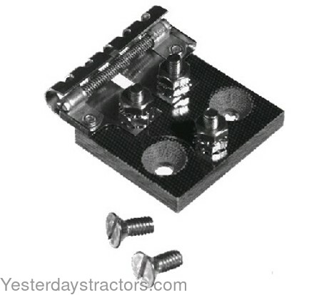
Bad Coil? 12v system, starts hard (1948 front mount dist.)

homer14

Member
Hi, this may be a simple answer. I've bee reading the forums about identifying and troubleshooting 12v coils prior to this post.

I have a 12v alternator conversion tractor and the coil I have no idea about. The only markings on this are Taiwan and "A". I am reading 5 ohms resistance on the pigtail and the top stud (this is the primary right?). I've read that the top stud to the metal tab (this is the secondary right?) should be about 7k ohms.

I have no continuity (and thus full resistance) on the stud to the metal tab. Is the coil bad?

My tractor sometimes starts and runs weak or dies if i add any throttle. It starts very hard and sometimes doesn't. I can usually only get it to run for a minute or two which maybe means the secondary coil is going bad I'm guessing?

I've cleaned out and reassembled the carb and dont think its the carb. I cant really fine tune the carb because i cannot get a stable running period and the ability to go full load or full throttle. I'm suspecting its the coil but I've also ordered the tune up kit on here with the plugs, wires, condenser, points, etc (not the coil) just in case its something else.

I've stopped here with the coil as the potential culprit pending your answers and feedback before going further onto checking the condenser points etc.
 
If the coil was bad it wouldn't run. I would suggest cleaning and adjusting the points and all the electrical connections. This includes the surface where the distributor mounts/grounds to the engine.
 
5 ohms on the primary is excessive. Should be about 3 ohms max.

7K on the primary is in range.

Now the question is it the coil or your meter? Short the leads of the meter together on lowest ohm scale. Note the reading. Check resistance across the coil primary and subtract shorted probe reading. This should be coil resistance.

If you are on too low an ohm scale it will read open on the coil secondary. You need to be on at least a 10K range
 

00.1 or 00.0 ohms when touching leads together.

Resistance was checked on 20k ohm scale, next one down is 2k ohm, tried them all. No beep on continuity would mean no way to measure any resistance too right?

If 5ohm's is high on the primary, thats not going to work either right since i would result in a weak spark along with the ballast inline?
 

So i tried a 2nd multimeter for giggles. this one starts at .5 ohms on primary, then slowly counts down to .323 and hovers around there.

This 2nd multimeter also shows no continuity on secondary.
 

I was thinking the same about running vs non running. then I wondered, is it possible it would be "going bad" as in the windings are barely touching in one spot or something and perhaps some shaking, banging, electricity to one side, or something weird makes it work once in a while, heck i dunno.

No continuity from two multi-meters on the metal tab to stud on top.
 
How did it run before you did a 12V switchover job? The 6V square can front mount distributor coil should check about 1.3 ? static; the 12V coil about double that. I'd say something else is wrong in the wiring. Do you have the OEM Ballast Resistor wired in correctly as it is OEM? Are you using the external 1-OHM ceramic resistor and a 12V coil? If so, remove this resistor. You only use the external resistor if using a 6V coil on the front mount system. Is the Voltage Regulator still in the circuit? If so, it shouldn't be, remove it. Is alternator 1-wire or 3-wire and wired correctly? You say 12V but is it correctly wired as NEG/GRN? Alternators like negative ground. Work on one system at a time. You can do a simple fuel flow test to determine if carb is getting fuel or not and no need to yank it off and rebuild until determined it should be. If carb passes fuel flow test it is good, move on to electrical, and forget it for now. Distributor is a standard unit with points with no funky EI setup, right? When was the last time you did a tune-up? Stop the guessing. Go about it like any other problem. Stop buying parts you may not need.

Tim *PloughNman* Daley(MI)
 

Hi,

I didnt do the 12v switchover, when I bought it, it was like this. It actually started up pretty good for a year or two and just started to have issues 2 weeks ago and major issues starting these past few days.

I have the coil out. I could make a video and show no resistance or continuity showing on the secondary if it helps.

I think I mentioned .323 when it probably was 3.23 ohm on my 2nd multimeter (auto adjusting scales). My first multi-meter showed 5 ohms. As far as the secondary, i get nothing from either multi-meter.

there is no voltage regulator in the mix.

the ground system is negative (converted).

I mentioned going through the carb. fuel flows fine and the carb has been cleaned and set to specs.

distributor is standard looking yes, no EI stuff.

I've never done a tune up, i mentioned i ordered a tune up kit on the electrical side but i didnt order a coil yet, however i think i may need to?

The alternator is a single wire. there is a little resistor between the 2 wire holes on the molex connector, with one wire coming out to the rest of the electrical system.

I dont know if its the oem ballast resistor. It's a long white skinny looking ceramic housing, inside it is a spring wound wire thingy with the two metal connectors sticking out. That measures about 1 ohm at about 55 degrees out + or - a few tenths.
 

the ceramic resistor is not the OEM. it's an add-on for the 12 volt conversion. if u end up needing a new coil, get a 12 volt coil and remove the ceramic resistor from the coil wire. it's only needed to protect a 6 volt coil from 12 volts. (i say 'needed,' but my 12 volt conversion still has a 6 volt coil and no ceramic resistor, got somewhere north of 150 hours of admittedly light duty on it.)

this is the OEM resistor:

wml_A8NN12250A.jpg


it mounts on the forward-facing surface of the dash.
 

I think the ceramic aftermarket one, as long as it is functioning with resistance (mine was about 1 ohm) , would still do the job yeah?

Isnt the goal to limit amperage to the coil to something like 3.5 amps by adding resistance to the coil?

This photo shows two resistors, the oem style one and a 2nd one (added for 12v conversion?).

http://www.myfordtractors.com/12volt03.shtml

I think the two resistors combined accomplish the reduction in amperage to the coil from what I read today. So I'm thinking if my coil is bad (the main question of mine in this forum post) and i get a new one then if i test the ohm resistance on the ceramic guy i have and the resistance on the new coil and it works out to limit the amperage to 3.5ish to the coil id be fine, no?

I may order one and follow-up with yall.
 

Thanks all for the tips. I've got a coil ordered. I'll follow-up in a few days or so.

I'm not sure how easy it will be to replace the condenser and points and all that with this front mounted distributor so that may slow things down.

Do any of you guys do that without removing any of the front end stuff or must that be done?
 

the distributor is held in place with 2 bolts. remove the coil and distributor cap, pull the 2 bolts and take it inside with u. when the time comes to put it back on, don't worry about the timing. the distributor will only go back on one way, thanks to an offset tang.
 

If I had a front mount dist I would keep a spare coil are two so no money wasted... I don't own a front mt and keep a 12 and 6V coil on the shelf. The coil can check good and be bad so a ohm check is not of much help. I would get a spark tester and learn how to use it it will come in handy... I have 6 are so spark checkers of different types they all come in handy 5 of'em don't lie one does but has its place it can be used...

I think you have a good understanding you just need a known good part to build a reference to...

While on FT MT coils :lol: look into modifying a old coil are do a Bob conversion to a round can coil...


https://forums.yesterdaystractors.com/viewtopic.php?t=1371138&highlight=coil

I have more post on it somewhere now a Bob conversion. I brought a $25 can of fiberglass resin just have not got around to it...

https://forums.yesterdaystractors.com/viewtopic.php?t=1371222
 
OK -good fuel flow so your next step is to move on to electrical. You haven't said if you have the OEM Ballast Resistor in the circuit, all wired correctly as OEM. That'd be the first step. HFJ has posted a picture of the OEM Ballast Resistor. If you do not have it, that is the only new part you need to buy. I?d also say your coil is most likely good so leave it alone. Front Mount Distributor tune-ups scare a lot of folks, but the truth is they are not difficult to do at all and a good learning experience. Go to the other Ford N-series Tractor site, the *N* - *T* - *C* and look at the top menu bar for the HOW-TO's forum, under electrical. You will find documents on doing a tune-up and also "WIRING PICTOGRAMS BY JMOR". All are available for FREE to download to your own PC. Use the latter to verify your system is wired all correctly. A new 12V coil is best to eliminate not having to use an external resistor. Forget about all these VOM readings you keep mucking with. The funny thing about FM coils is they can check good static, about 1.3 OHMS, but in actual use as they get hot, can fail. You would need sophisticated, expensive test equipment to truly diagnose if good or bad. One major reason why they fail is if the key switch was left 'ON' and the points were closed. This can melt the insulating tar inside them. As they get hot, the windings can short out. As they cool, they form a insulating barrier until heated up again. It could be why yours runs OK one minute and not the next. The front mount distributor tune-up is a workbench or kitchen table project. You do not remove the hood, radiator, gas tank, or doglegs. Yes, it?s true if they are already off, it is a bit easier to do, but unless a rebuild is in progress, no need to remove for a basic tune-up. Here?s how I do it: First is to clean off the unit and area with a spray bottle of mineral spirits and an air gun. I get all the accumulated dirt, grease, and crud off the external area to make it easier to handle. Next is to loosen the generator and slip the fan belt up over the fan blade out of the way then gently let the genny down out of the way ?you do not need to remove the entire unit. Loosen the coil wire from the coil post. Remove the plug wires. You can mark/number them with a piece of masking tape ?it?s important to know which wire is which when plugged onto the cap. FIRING ORDER is 1, 2, 4, 3, rotation CCW viewed from the front. I always take the coil off by slipping the bail down and removing it from the unit. Some fellas leave it on, I find it easier to maneuver the unit to get it off without. Two bolts secure the unit to the front timing gear cover. They are 5/16-18 x 7/8 long hex head bolts and you need a ?? combination wrench to loosen and remove the bolts with. There are lockwashers under the heads too. Keep them handy and cleaned off before re-installing later. The cam on the front mount has an offset tang. So does the engine front timing gear off the crank. It is designed so once the points are set correctly, your timing is set too. There is no mucking around with a timing light. It is, however, very possible to get the unit mounted 180? off, despite what others may say. If that happens, the moment you crank the engine, it will try to self-align and end up busting the distributor base around the cam tang aluminum housing. Don?t let that scare you. When you go to mount the rebuilt unit, you will verify the engine tang position and align the distributor tang exactly in the same position. Best to use a good LED flashlight and inspection mirror to get a accurate visual. Also, have a buddy verify tang locations as well just to get a second set of eyes on it. I always install the coil at rebuild after new points and condenser are set and unit has passed testing. Mount the unit back on by hand gently, feeling for the tang to slip in correctly. Unit should be flush with front cover face. Insert bolts, snug up each side equally then tighten down. Install wiring as was removed then reset the generator and fan belt. If you don?t feel up to doing your own tune-up, send it to me and I can do it for you. I have a few rebuilt units all set to go too if you elect to just do an exchange. It is up to you to do the removal and installation. The OEM Ballast resistor is mounted on the LH rear dash panel, near the AMMETER but when viewed from the front of tractor is on the RH side. I?d use the 12V coil you have, it most likely is good. Remove the external ceramic 1-OHM resistor altogether per WIRING PICTOGRAMS, 12V setup. You can find distributor tune-up instructions in the original 8N Operator?s Manual and the I&T F-04 Manual. Do you have them? If not, you might want to get them. You are on the right track, just need some basic guidance. It?s a learning experience but not impossible. I guarantee you I can get, and so can anyone else, any non-starting N going regardless if 6V/POS GRN or 12V/NEG GRN with a simple distributor rebuild/tune-up and a correctly wired electrical system. I do this at least once a month for customers, and have done hundreds of tune-ups.

FORD EARLY 8N ORIGINAL DASH WIRING. BALLAST RESISTOR LOCATED AT 7 O?CLOCK POSTION OF AMMETER:
fks1UnXh.jpg

FORD OEM WIRING DIAGRAMS for reference:
CfuUUP3h.jpg
rxNF128h.jpg
lz8RwfQh.jpg

Tim *PloughNman* Daley(MI)
 

Hi Tim,

Whew, thanks for the detailed response.

Yep, I have the manual you mentioned.

I mentioned in response to your earlier post that I have the long white ceramic looking resistor which isn't the OEM one it looks like per the above posts and photos. A picture of it is in the "12v conversion a la tisco" photo of JMOR's.

I think now I understand whats going on with my wiring side. The prior owner must have tossed the oem resistor block. He is using the ammeter post as the oem resistor block post (see my photo below). I suppose that doesnt matter much though?

He is using the non-oem resistor in the mix (i tested at about 1 ohm, not warmed up). If I wait long enough for my scale adjusting multi-meter on the primary of the coil it gets down to 2.32 ohms and hovers around that. So 1 ohm on the knock off ballast resistor plus 2.32 coil primary ohms = 3.32 ohms. Then 14.7v / 2.32 ohms would mean my coil was getting 6.3amps (and may be fried?)! Did I do that right?

The wiring on mine currently:
https://ibb.co/d8ZSOA

thanks for the tips on the tune up. I'll check them out when i get my parts.

I think my action items here are the following, comment welcome:

1. install new coil
2. install new oem ballast resistor (are these all knock off now?)
3. rewire to the oem ballast resistor
4. remove ceramic resistor
5. do the tune up kit i ordered just because.

Any tips on where to get the oem ballast resistor. I see them all over ebay and online but which ones are good? Maybe this place has them, ill check.
 

Just in addition to my post above since edits arent allowed and i had a typo in my example math on amps (I meant 3.32 not 2.32 in the example).

This site's resistor says the resistance is about .6 ohms:

https://www.yesterdaystractors.com/Ford-8N_Resistor-Assembly_A8NN12250A.html

If my ceramic resistor showed 1 ohm then my coil plus that 1 ohm = 3.32 ohms. So 14.7 / 3.32 = 4.42 amps to my 12v coil (3.6 - 4 desired?)

If the new oem ballast resistor above is .6, it gets worse for my coil. 14.7 / 2.92 = 5.03 amps to coil. Right?

It almost seems to me that if the desired amperage to the coil is supposed to be 3.6 to 4 then i actually need more resistance than just the oem ballast resistor to protect the coil but all of the diagrams out there show just that as Tim pointed out. Perhaps the recommendation of 3.6 to 4 amps the coil.

so fun. :)
 
"I'm not sure how easy it will be to replace the condenser and points and all that with this front mounted distributor so that may slow
things down.

Do any of you guys do that without removing any of the front end stuff or must that be done? "

No need to remove anything but the distributor itself! In fact I doubt that I could change the points and condenser on one of my eight front
mount distributor Fords if you removed the hood and the radiator. You need to learn how to do this or trade up for a more modern tractor. As
JMOR says, the coil is most likely not your problem.
 
(quoted from post at 07:53:19 10/23/18) "I'm not sure how easy it will be to replace the condenser and points and all that with this front mounted distributor so that may slow
things down.

Do any of you guys do that without removing any of the front end stuff or must that be done? "

No need to remove anything but the distributor itself! In fact I doubt that I could change the points and condenser on one of my eight front
mount distributor Fords if you removed the hood and the radiator. You need to learn how to do this or trade up for a more modern tractor. As
JMOR says, the coil is most likely not your problem.

Only two bolts hold the distributor on. Remove it and sit at the kitchen table while you work on it and set the timing. Reinstall. One hour job if you drink a couple beers. :)
 

We'll here's probably the issue leading to my coil going bad. I didnt go stare at the alternator wiring and assumed it was a single wire when the thing was right in front of my face.

https://ibb.co/dKK0Aq

It's a 2-wire setup! I found a 8n discussion on the delcto 12si and delco 10si alternators on another forum about the "2 wire alternator" setup as well. On mine, the coil has a wire directly from the alt bat terminal! That's probably fried my coil right there. Then there is a molex connector to the two terminals on top. The exciter terminal is jumpered to the voltage sensor terminal with a resistor as you can see in the pic, and the voltage sensor terminal is wired up to my electrical system.

Heh wild. Well, once i get my parts I'm simply going to rewire this puppy per the online manuals after doing the tune up kit and what not too.
 

Just an update. I pulled the distributor out, no problem, just as mentioned in your feedback. Originally I was thinking of an automobile distributor with the long shaft and gear at the end which made me wonder how the heck will I get that out of a front mounted 8n. It's a lot smaller than I thought and I should have googled some pictures of it to realize this before asking.

Once my parts come I'll rebuild it on the bench and check the old parts while I'm at it as they may be fine and worth keeping. I'll see if the ford manual has any details on checking each component before asking any questions. the new stuff will go in anyhow.

stay tuned and thanks again for the feedback!
 

New coil arrived. This one has successful resistance on the secondary from both multimeters I was using on my old one which showed nothing. Funny thing was one read 12k ohms and the other about 4400 ohms on the secondary. As you guys mentioned, this is expected with junky multimeters. Anyway, at least i see resistance now!

I noticed the new replacement coil has a primary pigtail that's quite a bit longer than the prior coil's pigtail, relatively speaking.

stay tuned, awaiting parts...
 
Got my parts. Rebuilt the distributor. I have one question on that front... see the round gasket in the photo below?

I didnt see one like that come off of anything and it doesnt fit nicely on anything except a tight fit between the cap and the distributor but that would hold out the cap from fitting in its seat with the cap key.

Is it meant for a rebuild of the other side distributor possibly and i dont need it?

https://ibb.co/gdG6RV

gdG6RV


After the answer to that, onto some rewiring work. Would 8ga or 10g be good for all of the wiring in regard to the alternator and coil end of things?[/img]
 

first thing: to embed an image in a post, u have to link directly to the image. the links u posted are to a web page with an image on it. the [img]https://image.ibb.co/kkBvLq/8nrebuiltdist.jpg[/img][/code:1:5d4057c58d]

[img:5d4057c58d]https://image.ibb.co/kkBvLq/8nrebuiltdist.jpg

8 or 10 gauge wire is fine for alternator output. for the coil wire, u don't need anything that heavy. i suspect 16 gauge would work, but use 14 to be sure.

i have no clue where that gasket goes.
 
I got a little anxious to try to start it. It started up in 1 second cold.

I'm lacking the oem resistor block below:

wml_A8NN12250A.jpg


However, i have the white ceramic resistor used previously which i understand has the same resistance as the oem one. The prior owner had the stuff that normally would be wired to the middle post on the oem resistor block, wired onto an ammeter post instead (probably due to lacking oem block).

So I did the same thing on my wiring check with my anxiousness to try to start the tractor with just the distributor rebuilt. I also removed the 1 and 2 terminal wiring thing they had with the resistor between the two and let it be a 1-wire system. It started right up! It no longer chokes instantly when I try to give it more gas either.

I've yet to install the kit's plug wires and plugs. I may just save them until they are needed or do it another day.

In the end it seems it was the ignition coil. The wiring setup currently is odd without that extra post (which would be available on the oem resistor block) but it seems ok this way for now too.

Thanks for all of the feedback and help. If anyone has any questions, comments, or concerns with what I've said thus far please let me know! :)
 

We sell tractor parts! We have the parts you need to repair your tractor - the right parts. Our low prices and years of research make us your best choice when you need parts. Shop Online Today.

Back
Top