MF135 Ignition headscratcher?

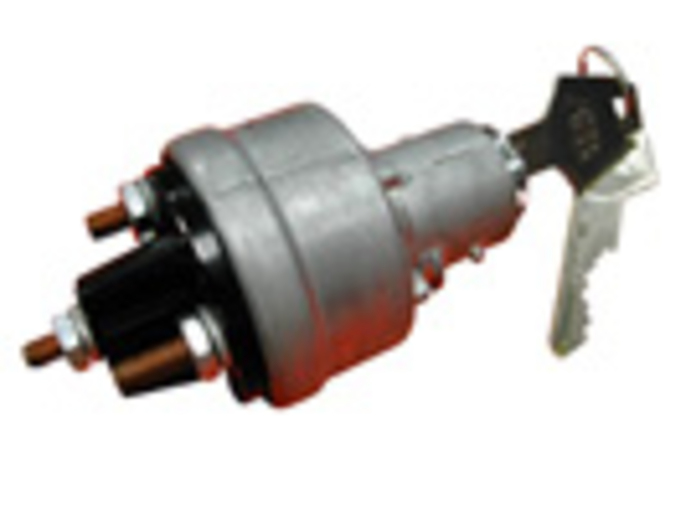
My MF135 is about to get an upgraded ignition switch, the one in this picture, a changeover from the two wire push button switch I suspect may be from 1972 or thereabouts. This new thing's got 4, count 'em...4, posts to hook up. Three of them are marked clearly on the back side: Battery, Ignition, And Accessory. This switch is a 4 position jobber: Off, far right for Ignition, self-returns to On after ignition, and Accessory at far left past Off.

Question: Is the prominent center post on the back a Ground connection or something different? If it is a Ground, is a Ground to the frame good enough? Should it be a home run to the negatory battery post? Or does the switch case provide the Ground connection? Even the wiring diagram that came on the package doesn't lay this out this too clearly. I just hate it when my wiring goes up in a puff of smoke with sparks flyin' everywhere! Thanks for your time and consideration...The Frontranger
a7371.jpg
 
I would expect the fourth post would be for the starter solenoid. When you turn the key to the start position it would put power to the solenoid to energize the starter. The ignition is powered in both the start and the run position. Easy to check if you have a volt ohm meter.
 
Fun question is that for a US 135 or for a UK 135? I forgot if you"re in the US or not butm ine has three prongs that come out that the plastic connector slips over and holds the harness against the plugs off the switch.

That doesn"t look like its the correct switch to me at least. I have a gas and I know you said you had the diesel. go to www.agcopartbooks.com and check the part number that switch is supposed to superceed/sub for against the OEM. I would get the OEM switch to be honest for as the Heritage parts have a one year warranty through AGCO.

my two drachmas...

Christos
 
Thanks for your comments. I'm in the USA, on the front range of the Rocky Mountains in Colorado. This is a '72 135 diesel, a little bit different from the gasser's wiring. My thinking on this switch: by the diagrams I have (OEM Operator's manual and IT shop manual), the original two wire switch had one wire going to one side of the ammeter that is also directly connected to the alternator with a 10 ga wire. The other wire from the original switch runs to the neutral (must be in full 2 stick neutral to start) switch and then to a seperate post on the starter solenoid all by itself. My current wiring corresponds to this exactly. The other (or 2nd post) post on the ammeter connects to the light switch (with a fused connection) and to the main power terminal on the starter solenoid which also is connected directly to the battery (a 2 ga. battery cable to the positive post on the battery).

I'm thinking this new switch's accessory post should be to power additional things that might get added to the electrical system, in my case a new fuse panel to make the connections through, and indirectly wired in through the voltage regulator as well. It may well keep me from having to walk home because I forgot to shut off something, because all accessories should be in the off position when the key is removed. It seems to me that even a generic one such as this ought to be sufficient to get the job done, and what I've seen at AGCO looks identical.

But this 4th, most rearward extending post in the center of the plastic casting on the backside is throwing me. I suppose it could be some kind of mounting post or some means to hold or attach a recepticle or something else, but it strikes me that it might be some kind of additional grounding lug...maybe..maybe not. Seems like one would want to take full advantage of any additional grounding potential if it is possible, Y?N? Drawing a complete blank here on finding any info on this point. Any other ideas? Thanks in advance...The Frontranger
 
My 1972 MF owner's manual, on page 44, shows the diesel electriical system (figure 62). The ignition switch in the diagram has 5 terminals, connected as follows:
terminal #1_ dim headlamps
terminal #2_bright headlamps
terminal #3_ vacant
terminal #4_inverter
terminal #5_ammeter

I do not have part #'s.
 
NOT GROUND! P Tibbetts is correct the extended center post is the starter solenoid activator post. It replaces the remote starter button in a self contained key switch.
 
Hey Ray: Thanks for the input. I've got the same book you do, and if you will look a little closer, you'll see you are describing the lighting switch. Same OEM Operator's Manual diagram, Fig. 62, item 15 is the Starter switch, post on left going to starter solenoid and ammeter, post on right going to the item 15, the Safety Start (Neutral) switch, then to the pository post on the battery. This is a diagram for a unit with a generator as opposed to an alternator. Another drawing I have indicating correct wiring layout for a diesel machine with an alternator has the neutral safety switch wire going to the "S" post on the solenoid, which incidently is exactly how mine is wired now (it came to me this way and works just like you'd want it to).

A couple of helpers on this thread are suggesting the 4th post should go directly to the solenoid, and that is leaving me wondering what to do with the ignition post... ideas? With appreciation, Yerz, the Frontranger
 
Thanks Pete!Your suggestion is gaining better traction with me, does make some sense, but is leaving me wondering what to do with the IGN post on the switch. The ACC post ought to be a seperate element, more or less, I would think, making it possible to add other circuits to be controlled from the ignition switch, On when the key is On and Off when the key is Off, except for when the key is turned all the way to the far left, the Accessory position.

The battery post, BAT, seems clear enough, should go to the ammeter post that will allow for a direct connection to the pository battery terminal through the ammeter switch. Am I reading this wrong? Thanks again, The Frontranger
 
(quoted from post at 09:42:53 11/30/09) Thanks Pete!Your suggestion is gaining better traction with me, does make some sense, but is leaving me wondering what to do with the IGN post on the switch. The ACC post ought to be a seperate element, more or less, I would think, making it possible to add other circuits to be controlled from the ignition switch, On when the key is On and Off when the key is Off, except for when the key is turned all the way to the far left, the Accessory position.

The battery post, BAT, seems clear enough, should go to the ammeter post that will allow for a direct connection to the pository battery terminal through the ammeter switch. Am I reading this wrong? Thanks again, The Frontranger

IGN is for connection to (obviously) the ignition coil of a gas engine. The ACC should be used for any other accessories.
On your diesel I am not sure what it would connect to if anything.
Prior to this upgrade, what did you use to stop the engine?
 
Thanks Inno: The diesel has a kill button you pull which effectively floods the diesel injection pump, nothing electrical about it. And I am beginning to suspect that you are correct about the IGN post not necesarily having anything connected to it in my case, unless that just won't work without some kind of connection. Probably, I have hornswaggled myself by buying a switch that is not particularly well suited to my needs here. But being the tightwad that I am, I will probably go ahead and use it anyway, leave the IGN post open (maybe with an insulating cap) and be content with the outcome as long as it works. Unless I discover some downside to this possible way of using it. It is a heavy duty 15 Amp unit and should be up to some extended duty if I don't fry it or something else in the process.

My initial goal was to gain the ACC post for adding some lights and flashers that the MF 135 did not come with, and I may still be able to do this even in this situation. Any additional input will be appreciated, just as evrything else YT folks have posted here. Thanks again, The Frontranger

PS: Latest developements
FYI, I broke down this AM and dug out some un-used 12V bulbs out my junk electrical box, soldered individual wires to their base and middle contact points (2 wires per bulb), put some test aligator clips on the center contact point connector wires and clipped one to each post, all 4 of them. Also hooked up a 12V supply from D cells (8 of them hooked together) and wired all the base contact wires from all the bulbs and the negatory (-) post on the battery supply together with a house wiring connector, and put the power connect (+) from the batteries to the BAT post.

The result: In the OFF position, only the BAT light lit up (as it should be, I think, a single complete circuit w/ one bulb in it); In the ON position, the BAT, IGN, and ACC lights lit up; In the START position, the BAT, IGN, and the #4 REAR POST lights lit up, and the ACC light goes off. When the key is released, the #4 goes out, and the ACC comes back on, along with the BAT, and the IGN lights. In the ACC position, far left position past OFF, only the ACC and the BAT lights came on ( somehow this seems right too). So I have discovered that the back #4 post is electrical, and probably should go to the solenoid.

But my machine is a diesel, and there is no iginition coil on a diesel. So in my case, if I decide to use this particular switch, I apparently will have an open un-used connection on the IGN post, unless I can figure out what ought to be put there, if anything else needs to go there. This might be OK, operational, and otherwise still a workable way to go with this particular switch. (Scratchin' my head and chin together now!). It looks like I might not need to use that post at all, as only two wires need to hook up from the Ignition switch to the starter at the solenoid, I'm thinking the BAT and the #4 mystery post that only comes on in the start position.

I'm still just a bit in doubt if this will still result in a useable switch, or will I need to just go get a different switch w/ 3 posts instead of 4. Still working this out and looking forward to what your friend might have to say. Thanks so much for your input and time and consideration...The Frontranger
 
(quoted from post at 14:16:10 11/30/09) Thanks Inno: The diesel has a kill button you pull which effectively floods the diesel injection pump, nothing electrical about it. And I am beginning to suspect that you are correct about the IGN post not necesarily having anything connected to it in my case, unless that just won't work without some kind of connection. Probably, I have hornswaggled myself by buying a switch that is not particularly well suited to my needs here. But being the tightwad that I am, I will probably go ahead and use it anyway, leave the IGN post open (maybe with an insulating cap) and be content with the outcome as long as it works. Unless I discover some downside to this possible way of using it. It is a heavy duty 15 Amp unit and should be up to some extended duty if I don't fry it or something else in the process.

My initial goal was to gain the ACC post for adding some lights and flashers that the MF 135 did not come with, and I may still be able to do this even in this situation. Any additional input will be appreciated, just as evrything else YT folks have posted here. Thanks again, The Frontranger

PS: Latest developements
FYI, I broke down this AM and dug out some un-used 12V bulbs out my junk electrical box, soldered individual wires to their base and middle contact points (2 wires per bulb), put some test aligator clips on the center contact point connector wires and clipped one to each post, all 4 of them. Also hooked up a 12V supply from D cells (8 of them hooked together) and wired all the base contact wires from all the bulbs and the negatory (-) post on the battery supply together with a house wiring connector, and put the power connect (+) from the batteries to the BAT post.

The result: In the OFF position, only the BAT light lit up (as it should be, I think, a single complete circuit w/ one bulb in it); In the ON position, the BAT, IGN, and ACC lights lit up; In the START position, the BAT, IGN, and the #4 REAR POST lights lit up, and the ACC light goes off. When the key is released, the #4 goes out, and the ACC comes back on, along with the BAT, and the IGN lights. In the ACC position, far left position past OFF, only the ACC and the BAT lights came on ( somehow this seems right too). So I have discovered that the back #4 post is electrical, and probably should go to the solenoid.

But my machine is a diesel, and there is no iginition coil on a diesel. So in my case, if I decide to use this particular switch, I apparently will have an open un-used connection on the IGN post, unless I can figure out what ought to be put there, if anything else needs to go there. This might be OK, operational, and otherwise still a workable way to go with this particular switch. (Scratchin' my head and chin together now!). It looks like I might not need to use that post at all, as only two wires need to hook up from the Ignition switch to the starter at the solenoid, I'm thinking the BAT and the #4 mystery post that only comes on in the start position.

I'm still just a bit in doubt if this will still result in a useable switch, or will I need to just go get a different switch w/ 3 posts instead of 4. Still working this out and looking forward to what your friend might have to say. Thanks so much for your input and time and consideration...The Frontranger

Yes to all!!
I think you've got it figured out. There is no need to connect the IGN post to anything but you certainly could use it to power any accessory you want on with the tractor running. Really this type of switch is not necessary for a diesel engine tractor. Aside from giving you key starting instead of pushing a button there are no benefits. You will still have to use the original pull button to kill the engine.
You would have been better off with simple switches (with appropriate fuses) for the circuits you want to add.
However, with this switch, as you said in an earlier post with the key removed it will shut off all your accessories and prevent you from killing your battery.
You can most definitely use this switch and for the previous reason, I would use it. Not to mention that it can not be started without the key in the ignition if you choose to use the start feature (post#4) instead of a push button.
 

We sell tractor parts! We have the parts you need to repair your tractor - the right parts. Our low prices and years of research make us your best choice when you need parts. Shop Online Today.

Back
Top