1963 John Deere 1010c gas engine

John1010c

Member
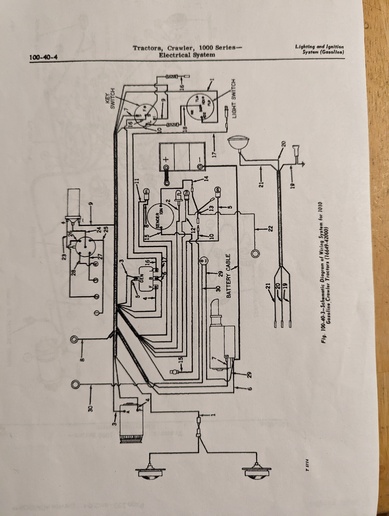
Does anyone have an early wiring diagram
for a 1010c that shows using a ballast
resistor ? Would be very appreciated.
 
(quoted from post at 17:08:34 01/28/23) Does anyone have an early wiring diagram
for a 1010c that shows using a ballast
resistor ? Would be very appreciated.

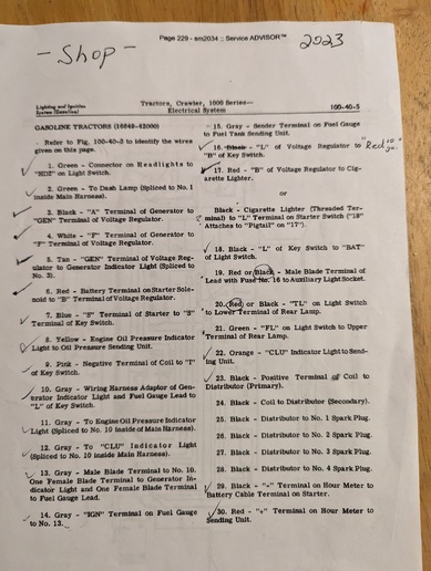
I don't have one and haven't been able to find one. Are you asking about the ballast resistor mounted on the original switches or a separate ballast resistor? The 2010 service manual says if the resistor is bad the switch has to be replaced. I don't think the original switch mounted type shows in the wiring diagrams as it was a part of the switch. There was a switch and resistor kit that substituted for the switch with the mounted resistor. It appears there was an instruction sheet with that kit (JD # DUB-455) but I haven't found a copy to verify that. The resistor does not show up in the wiring diagrams. You may need "wing" it on this one.

Looking at the ignition switch kit in the parts catalog it would appear that the kit included a small, short harness which allowed the resistor to be bypassed right from the ignition switch during starting.

Basically, one terminal of a separate ballast resistor would be powered from the "I" terminal of the ignition switch. The other terminal would be wired to the coil. Later wiring ran a wire from the "I" terminal on the Delco starter solenoid to either the resistor terminal with the wire going to the coil, or direct to the coil terminal with the wire from the resistor.

I don't know if this helps. If not, would you explain what you are trying to do in more detail. It does appear that at least some replacement switches are available with the resistor mounted on the switch, like the original type.
 
Thank you very much for taking the time to
respond. Basically the root issue is when I
hook up the new OEM switch and try to start
the machine it will fire up but immediately
die when I let go of the key. Obviously
it's not getting fire in the run position.
This is a complete remodel so everything is
new. Unfortunately the previous owner had
it wired different than what the book shows
so no help there. Currently there isn't a
ballast resistor because I thought I could
use a coil with one built in to it. Another
thing to note is if I move the I wire to
the F terminal on the switch it will stay
running but the book says F isn't used. I
would like to keep everything as original
as possible.
One question you did clear up is which and
how many wires go to that ballast resistor
. I found someone that said they have the
correct switch but I can't remember if it
had the resistor built on the switch or
not.
 
(quoted from post at 00:16:06 01/29/23) Thank you very much for taking the time to
respond. Basically the root issue is when I
hook up the new OEM switch and try to start
the machine it will fire up but immediately
die when I let go of the key. Obviously
it's not getting fire in the run position.
This is a complete remodel so everything is
new. Unfortunately the previous owner had
it wired different than what the book shows
so no help there. Currently there isn't a
ballast resistor because I thought I could
use a coil with one built in to it. Another
thing to note is if I move the I wire to
the F terminal on the switch it will stay
running but the book says F isn't used. I
would like to keep everything as original
as possible.
One question you did clear up is which and
how many wires go to that ballast resistor
. I found someone that said they have the
correct switch but I can't remember if it
had the resistor built on the switch or
not.

Firing up and running when you start it, then dying, when you release the key from the start position indicates the terminal you are using for ignition is the resistor bypass terminal in that switch. You said purchased a 12-volt coil, wound internally to provide the proper resistance, you do not need a ballast resistor. Not having a resistor will not keep it from running. You should not use that bypass terminal of the ignition switch.

Can you sketch at back of your AT21567 switch (show the location of the terminals as they are marked on the switch) and post pictures of your sketch and the back of the switch? From what I have found the "F" terminal was used to provide power to the fuel gauge on some machines, so it should turn on and off at the same time as the "I" ignition terminal. Have you used your voltmeter to check continuity between terminals of the switch in all the key positions? Based on what you have posted to date, I would wire the "F" terminal to the coil and run it.

If you go back to the original type of switch with the resistor, you will need to install a coil requiring a resistor for use on a 12-volt system.
 
Good morning and thanks for the comments. I
will try to provide a picture and a sketch
of the switch. If you could clarify this
for me please. If I go back with an
original switch that has a resistor on the
back of it them I will still need to
install a ballas resistor between the
switch and coil ?
 

No, the resistor on the switch is the ballast resistor. You do not want to add another ballast resistor.

You will need a coil designed to use with a ballast resistor. Using a ballast resistor with a coil designed to be used without an external resistor will put too much resistance in the ignition circuit.
 
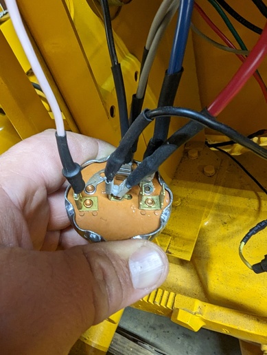
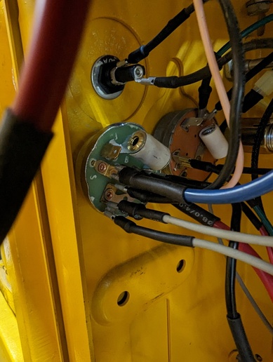
This is what I used to wire my machine. I
kept all the colors the same.
cvphoto146252.jpg


cvphoto146253.jpg


cvphoto146254.jpg
 
(quoted from post at 16:07:42 01/30/23) This is what I used to wire my machine. I
kept all the colors the same.
<img src=https://www.yesterdaystractors.com/cvphotos/cvphoto146252.jpg>

<img src=https://www.yesterdaystractors.com/cvphotos/cvphoto146253.jpg>

<img src=https://www.yesterdaystractors.com/cvphotos/cvphoto146254.jpg>

Do you have it wired so that it runs with the switch in your picture?

I am assuming the terminal the blue wire is on is marked "S". What is the terminal the black wire and gray wires are on marked? I am assuming the wire that I see as white, is pink and on the "I" terminal.

Are you looking at getting a switch with the resistor made on it? If so, you understand your new coil (which does not require an external resistor) will not work with that switch?

Have you taken an ohmmeter, or continuity tester, and checked which terminals have continuity between them in each key position? Keep one lead on the battery terminal of the switch when testing. If you do not have continuity between the center battery terminal and the I terminal, when the key is in the on position, the switch is defective.
 
Yes the white looking wire is actually
pink. It is hooked to the I terminal on the
switch and goes directly to the coil. All
the grey wires are for dash lights or
sending units. The instructions had some of
them spliced into other grey wires, I just
made the connection at the switch. I have
checked continuity and voltage to see
what's hot and the I terminal is only hot
during the start position. The F terminal
is hot in both start and run. The blue wire
goes to the S terminal. The black wire
powers the light switch. Yes sir I will
swap coils when the new switch arrives.
 
(quoted from post at 19:24:42 01/30/23) Yes the white looking wire is actually
pink. It is hooked to the I terminal on the
switch and goes directly to the coil. All
the grey wires are for dash lights or
sending units. The instructions had some of
them spliced into other grey wires, I just
made the connection at the switch. I have
checked continuity and voltage to see
what's hot and the I terminal is only hot
during the start position. The F terminal
is hot in both start and run. The blue wire
goes to the S terminal. The black wire
powers the light switch. Yes sir I will
swap coils when the new switch arrives.

Your earlier thoughts of a batch of defective switches very much appears to be correct.
 
Wanted to follow up on this issue. I purchased a switch #B5003-016 (their part number) from The Brillman Company. It seems to have fixed the issue with the ignition switch not staying hot on the run cycle. It has a built-in resistor so I had to swap back to the original coil .
 
(quoted from post at 15:48:00 02/04/23) Wanted to follow up on this issue. I purchased a switch #B5003-016 (their part number) from The Brillman Company. It seems to have fixed the issue with the ignition switch not staying hot on the run cycle. It has a built-in resistor so I had to swap back to the original coil .

Glad to hear you got it running again. Thanks for posting the cure.
 

We sell tractor parts! We have the parts you need to repair your tractor - the right parts. Our low prices and years of research make us your best choice when you need parts. Shop Online Today.

Back
Top