JD 520 Wiring Problems

Brian Donley

New User
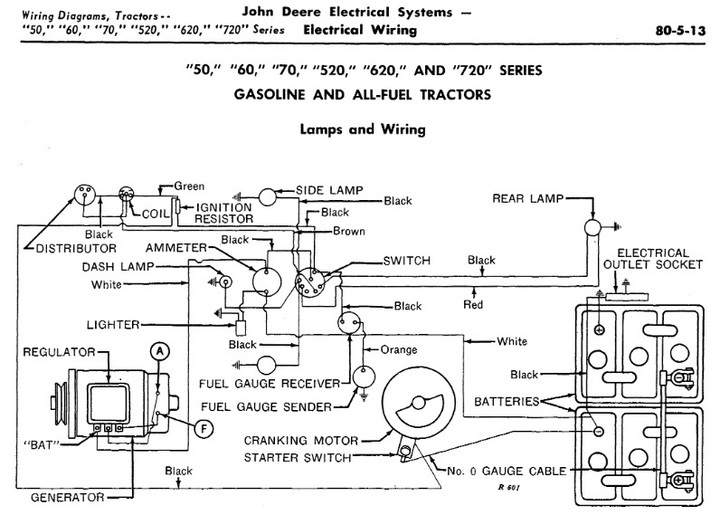
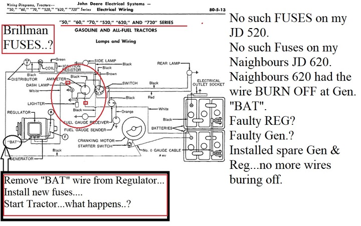
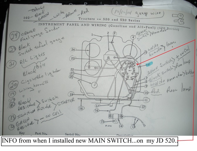
Looking for assistance. Recently completed a restoration of a '56 JD 520, (positive ground w/electronic ignition). The tractor started and ran fine for about 5-10 minutes and cut off. Two in-line fuses were blown, one from the battery to the ammeter (looking from behind the dash, attached to the left post) and the other from the combo switch to the ammeter (attached to the right ammeter post). In a phone conversation with Brillman, these wires are where he said they go. I have no frayed or damaged wires that would cause a short. I know little about automotive electric. I need someone who can talk me through the wiring connections. Can someone help me?
 
If it has blown fuses there is a serious short somewhere. Do you have a multimeter? Start disconnecting wires and measure each one for a short (zero ohms) to chassis. Did you buy a new harness from Brillman?
 
Was your '56 JD 520, positive ground "electronic ignition" ordered specifically for a a POSITIVE GROUND charging system?

Bob..
cvphoto59572.jpg
 
Hey Bob! Thanks for you reply. To answer your question, yes, the electronic ignition was purchased for a positive ground prior to the disassembly. I ran the tractor for over a year before beginning the restoration. As a matter of fact, after the restoration I started the tractor and moved it out of the garage to allow the paint on the exhaust manifold to "burn off." It sat in the driveway idling for 5-10 minutes and then just quit. An inline fuse from the battery to the ammeter was blown as well as an inline fuse from the ammeter to the combo switch. Thanks for the wiring diagram. I will review it again. It just seems strange that it started, ran fine and then the fuses blew and quit. Any thoughts?
 
Hey Ron! Thanks for your reply. Yes, I bought the wiring harness from Brillman's. When my father passed away I got his multimeter. Unfortunately he never showed me how to use it and there are so many positions on it I don't know where to begin.
 
I live in High Point, NC. I'm going to phone a retired HVAC friend today who restores antique cars. I'm hoping he can come by and help me figure it out.
 
When and If my JD 520 starts to burn wiring up etc,etc,I shall do as per electrical schematic suggestion..

Bob..
cvphoto59600.jpg
 
Tell us the make and model of multimeter (also a picture of the positions if you can post a photo) and we can give further operating instructions. Use the low Ohms position to check for shorts to chassis, with one meter lead touching tractor chassis (frame) and the other meter lead touching the wire you have disconnected. When you find a "zero" or very close to "zero" reading you have found your short.
 
Was there a fuse between battery and ammeter prior to restoration? My model 50 does not have a fuse in that line and I find it strange if that's factory for a 520.
 
Which coil line are you measuring? and are you measuring through the coil or from one of it's terminals to chassis?

There are 2 circuits in a coil - the low voltage from ignition switch through coil to the distributor and back to chassis; the second is the high voltage from center heavy wire to the distributor to spark plug and return to chassis.

Your description of the one fuse location (fuse between ammeter and ignition switch) could cause a fuse to blow if the coil primary is shorted to its case and therefore to tractor chassis.

Need a bit more description of how and where you are measuring the 0.0 ohms associated with the coil.

Were the fuses in the lines before you did the new harness? Wonder if Brillman places those fuses in new harnesses?
 
Quote:
Two in-line fuses were blown, one from the battery to the ammeter (looking from behind the dash, attached to the left post) and the other from the combo switch to the ammeter (attached to the right ammeter post). In a phone conversation with Brillman, these wires are where he said they go.
cvphoto59740.jpg
 
You appear to be someone very familiar with electricity and obviously, I am not. Someone had to show me how to use a multimeter.

I installed a complete electronic ignition system kit from Steiner (Pertronix w/3 ohm coil and new wires). The tractor ran great. The tractor was torn down for restoration and I purchased a new positive ground wiring harness from Brillman that came with the inline fuse from the ammeter to the ignition switch. The gauges were purchased from Evergreen. After melting the wires twice from the battery terminal to the ammeter I installed an inline 20 amp fuse.

Regarding the testing of the coil, I removed the coil and tested continuity from the center post of the coil to the negative post and it read 9.53. Tested continuity from the center post to the positive post and it read 9.53. Tested between the positive and negative posts and it read 0.0. A technician at Steiner said it should read at least 3 ohms. I have tested the continuity of all the wires except the wires that go to the inside of the distributor and they all test fine.

Perhaps this after church I can try to get pictures of the instrument panel wiring to see if I have wired something improperly. Thanks SO VERY much for responding. As you can tell, I know VERY little about electricity except that it hurts to get shocked.
 
Thank you. I am an electrical engineer (mostly electronics, TV and radio) and have repaired several tractor electrical systems, my own and for friends. I try to help folks here, but it is hard to explain and ask correct questions for answers to move you on to the next step.

So based on what I understand so far for your problem, I would try a new coil. As the Steiner tech said, you need a small resistance between the + and - posts. That is the primary side of the coil and 3 or 4 ohms is what it should measure IF it's a 12 volt coil. But 520s came from the factory with a 6 volt coil and resistive bypass so you need to be sure which coil you have and if the bypass is there and working correctly. A true, good 6 volt coil will have less resistance than a true 12 volt coil.

I better quit until you know for sure what coil you have and whether it's good or not.
 
An electrical engineer!! wow! That's fantastic! (I'm a retired Army chaplain) Do you have an email address other than through YT? If so, I'll send you the PDF of the wiring. I can't seem to attach it to this email. You can email me at [email protected]

When the new coil arrives I'll measure between the + & - posts and let you know how many ohms it shows.

Taking pictures of the wiring behind the dash was about as helpful as trying to understand a plateful of spaghetti so I decided to draw how I've wired the combo switch and ammeter. The fuel gauge on the far left has three posts, ignition, sending unit (wire not shown), and ground. The color of the wires is for reading clarity only.

There is a ceramic "thing" (technical term) on the combo switch. One side is labeled HD but the other side has no label. Is it HD, as well?

Do I need a wire to the "ground post" on the combo switch?

Does this look correct?
 

We sell tractor parts! We have the parts you need to repair your tractor - the right parts. Our low prices and years of research make us your best choice when you need parts. Shop Online Today.

Back
Top