No oil to tappets

crawler

Member
I have a B 68215 serial. It has a tube going to the valve cover to supply oil to rocker arms. But it just spits out air no oil. the oil pressure gauges work. It pulsates like compression. Not sure where to look next. Could fan shaft cover or weight cover be out of time? How does the oil get to the tube? It does not have the disk and tube that bolts under the valve cover.
 
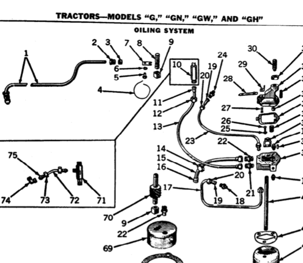
Try taking the fitting for the oil pressure gauge put and using a stiff wire see if you can get it to come through the other side of the governor case where the pipe going to the
tappet cover goes in. There should be a small hole in the shaft that works like a pump to get oil to the tappets. You might have to turn it over to align the hole. They
sometimes get plugged and stop up the oil. Parts book doesn't show this part but does show the pipe your talking about. Also it shows the oil line coming from the block that
is supposed to oil them. Both show the same serial number breaks so don't know what the deal is.
cvphoto57444.png


cvphoto57445.png


# 8 is the part that my need cleaning if you have that. Picture is from a G.

cvphoto57446.png
 
If your tractor has the tube from the governor housing to the valve-cover, then the oil to the rocker
arms comes down the tube gravity feed.. Your problem is the little trough inside the governor housing that
collects this oil is full of oil-sludge and dirt.. The trough needs to be cleaned out so it can catch oil
slung off the governor drive gear...
 
Wrong - the vent tube from the valve cover has nothing to do with oiling the rocker arms. It's the suction side of the ventilator pump on the fan shaft that clears engine vapors and then pumps them into the air cleaner instead.

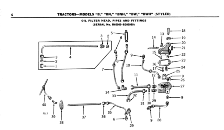
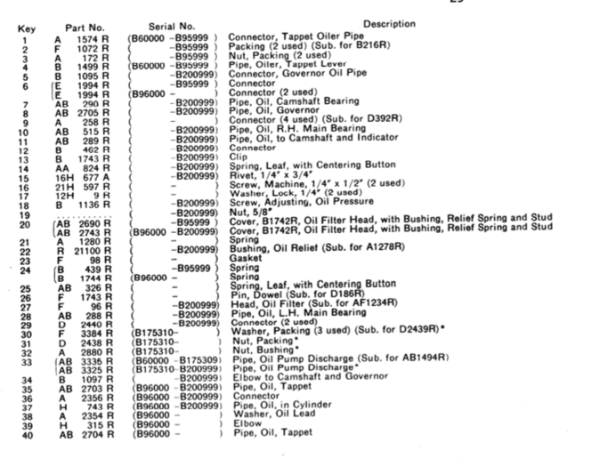
The oil supply for your rocker arms comes from the oil pump with a plot twist. MSD diagram of page 6 (top picture of B parts) shows the parts as numbers 35 thru 40. "Missing" disk (#38?) and "tube" (#40?) are absolutely required in order to oil the rocker arms. "Missing" disk (#38?) is a specialized cast iron washer with channels, that goes under a central head stud nut. It's used to gather the rocker arm oil supplied by tube #37 to that central head stud in the block proper.


The oil is reduced in volume by having to flow thru the oil pump shaft via a hole drilled thru it. This hole can sludge up preventing the flow of any oil at all, otherwise it gets only a very little amount of metered oil by the hole turning into alignment. Other things that can be wrong is to use a standard shaft without a hole in it for a replacement oil pump shaft, or using it upside down.

A blast of shop air as you turn the oil pump shaft by hand might clear the sludge from the hole and return flow to the rockers in short order. Remove tube # 35 to gain access for the shop air to blow thru the metering hole first.
 
Because mistakes can be made - it's not a lever but a sealed tube and you never move it as a lever. BUT the cartoon of it sure does look a lot like a possible lever.

WE have to choose from the data presented, is it a lever or a vent tube? I'll vote for vent tube. So I can't tell you how to get any tappet oil out of it since it doesn't do that.

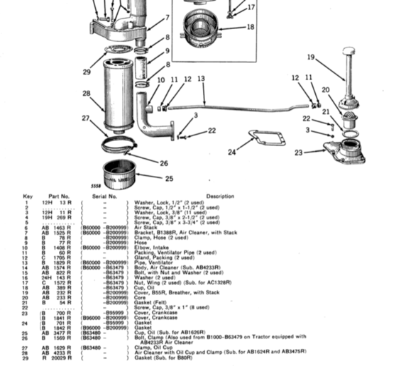
You've discovered a quite rare instance of a mistake in print that will never be corrected unfortunately, pipe #4 has nothing to do with tappets, oil or levers. It's clearly used as a vent tube for those tractors equipped with a fan shaft driven ventilation pump mounted to the governor housing. My 44 A has no #4 lever, but it does have proper rocker arm lubrication via methods that I've already described. It also has no ventilation pump on the fan shaft. I'm pretty confident that #4 and the vent pump go together and #4 is a vent pipe only.
 
No 4 is the pipe that carries oil from the governor housing to the tappet levers or the valves-rocker
arms. Look at your tractor.. above pipe # 4 is another pipe that is the vent pipe from governor housing to
the elbow bolted in front of the carburetor.
 
Take that description and add commas between words and read it like tube, for oiling tappet levers-more commonly called rocker arms. The tube you have is NOT a vent tube but is for oil to rocker arms. Your rocker assy cover is cast and has a troth in it to direct the flow. Also, know that the parts diagram covers 2 models, sn 60000 to 95999 and 96000 up to 201000. As you spend time using the parts lists you will be aware of the serial number breaks. This is one feature of working on old John Deere equipment, they had very complete and accurate data which makes working on them some 50-75+ years later a whole lot easier.
 
I think they are referring to #4 as an oiler pipe for the tappet levers or as commonly called tappets. Notice # 1 refers to a connector for tappet oiler pipe also.
cvphoto57615.png


# 13 is a vent pipe that goes from the governor housing to the air cleaner on serial #'s 60000 on up.

cvphoto57616.png
 
Yes; that is the oil trough inside your governor.. Do you need help if the governor governor shaft
has to come out??
 
That is NOT a vent pipe. I have a 39 B and #4 in the diagram is the oiler tube for the rocker arms. It is not an error in the parts book. There are two holes on the flywheel side of the governor on a 39 B. The top is for the vent and the bottom is for the rocker oiler tube. It was built like that from B1000 to B 95999. Oil will seep out of the governor housing gully (bottom hole) and drip slightly on the rocker arms from that tube. The top hole in the governor is for the vent tube going to the air intake. That sucks crankcase gasses into the intake to vent the crankcase. The break for 1941 occurred at sn# 96000 on the B. That is when the oil was piped in through the block and into the head to the rockers eliminating the external drip oiler and adding pressure fed oiling to the rockers and valves. Even after the bottom hole in the governor was deleted the top for the vent like the 35 to 40 B was retained. The vent pump did not show up until 1946 with the advent of the late styled tractors at serial # 200000. That tube went in from the front of the rocker cover to the intake pipe of the fuel system. I know because I have or have had had all 3.

The A's were the same design as the B's 34 to 40 were two holes in the governor....41 to 47 1 hole....47 was the vent pump run off of the fan shaft gears.

In the OP's case the gully where the oil is splashed into may be full of gunk and the oil cant get to the pipe. You can try to blow it out but taking the governor off of the tractor (fairly involved job) or removing the governor shaft weights and gear will give enough room to get it cleaned up.
 
Yes, you do need to time for removing governor shaft. Also, I would set timing of governor shaft
before I would take off the left end governor cover to look inside... Here is what you need to do.. Turn
the engine so you are on number one piston is top-dead-center.. On magneto, take off cover; is the rotor
pointing to no-one spark-plug wire. It should be... Next; you can remove the governor housing left end
cover. Catch the bearing and try to save the shim gaskets on cover.. Take a look inside housing, can you
see the trough?? If so, is the trough full of sludge-dirt?? Or is there no oil or oily surface inside the
housing?? If need to pull shaft to see, mark governor gear teeth where teeth mesh with camshaft, there
timing. Next; take off magneto.. Unhook throttle rod and rod off leaf spring on top of governor housing so
you can rotate governor shaft. Now you can pull out the gov shaft with gear and weights.. Make good marks
for timing so they will stay visible...
 

We sell tractor parts! We have the parts you need to repair your tractor - the right parts. Our low prices and years of research make us your best choice when you need parts. Shop Online Today.

Back
Top