
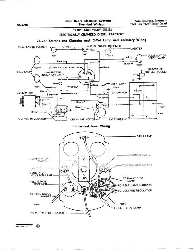
Hi, we are completely rewiring a 730D on 24 volts. The red generator light on the dash is on even when the ignition switch is OFF. When we remove the frame ground from the center connection off battery A positive post, it goes out. We have used the wiring diagram posted by one of the members here and have checked it against the factory wiring diagram and it all seems to be correct. What are we missing???
You are using an out of date browser. It may not display this or other websites correctly.
You should upgrade or use an alternative browser.
You should upgrade or use an alternative browser.
- Thread starter dvtw79
- Start date
Tx Jim
Well-known Member
- Location
- Coyote Flats, Texas
The 12 V generator light should go out when frame wire is removed because technically that wire should be the lights only access to complete the 12V circuit. Have you checked starter for brush dust?
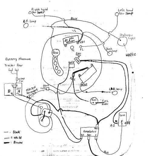
TX Jim, we did wire a ground wire to the indicator light. We stripped a ground wire and wrapped it around the little fingers of the backside of the red jewel light where it is a "spring" fit into the dash. We thought all the lights should have a ground. We did this with all the dash lights. The dash lights are working correctly. Also, we added an amp meter between the indicator light and the switch (I think it is BAT A on the switch).
Tx Jim
Well-known Member
- Location
- Coyote Flats, Texas
No "extra" ground wire should be required on gen light or dash lights because they should ground by way of the dash.
Understand, but my dash is all painted with new paint and instead of risking a poor ground, we grounded the indicator light, the dash lights and tach light to a frame ground on the steering pedestal.
I failed to answer your earlier question, the starter has been apart and new brushes installed. Shouldn't be any brush dust in the starter.
Still not sure why the generator light stays on when we hook up the frame ground at the battery with the ignition switch in the OFF position.
I failed to answer your earlier question, the starter has been apart and new brushes installed. Shouldn't be any brush dust in the starter.
Still not sure why the generator light stays on when we hook up the frame ground at the battery with the ignition switch in the OFF position.
Tx Jim
Well-known Member
- Location
- Coyote Flats, Texas
Have you tried disconnecting the wire on the ign switch that attaches to to the "gen terminal"?
I agree (as usual) with Tx JIm. The ONLY wires I figure that attach to the idiot light are the one from GEN on the VR to the switch terminal that appears to be labeled GEN?? NO WIRE FROM IDIOT LIGHT TO ANY EXTRA MADE FRAME GROUND
The idiot light is wired essentially across the cutout relay inside the VR and when it closes (as it does when genny is working) the voltage is equal on both sides so no light. However when the relay is open (gen not charging) theres voltage on one side but not the other so it lights up.
Up at the switch there are A and B 12 volt feeds (one Pos ground other Neg ground) to operate 12 volt lights, so if a light gets wired via EITHER of those switch feed to frame ground it will light up
IF YOU HAVE THE IDIOT LIGHT FRAME GROUNDED I THINK THATS INCORRECT see if theres a switch terminal (labeled GEN or???) and then if the other light wires leads to the VR's GEN terminal
John T
Tx Jim
Well-known Member
- Location
- Coyote Flats, Texas
If you disconnected wire at ign switch marked "gen" then it has to be getting electricity feedback through the VR if all other wires are connected correctly and have good insulation.
If that light, which is supposed to be wired ONLY to GEN on VR and Gen on switch, still glows with one wire unhooked, YOU HAVE WHAT AMOUNTS TO A PERPETUAL MOTION MACHINE.
If one side has a connection somehow to frame ground and the other side somehow (via the A/B 12 volt feeds to switch) sees 12 volts, it would obviously glow.
IM SORRY if there armed with a test lamp and voltmeter I may?????????? be able to help but thats the problem with these hode pode wiring rats nest 24 volt systems ITS HARD TO HELP PEOPLE OVER THE INTERNET........
John T
So we shouldn't have 12 volts at the voltage regulator ARM post? Would that imply the voltage regulator is bad (if all other connections are correct and insulated as you stated)? The gen light was working correctly when we stripped all the old wiring off, so we weren't thinking the VR is bad.
We do have a multi-meter. We did probe the ARM terminal and the RETURN on the VR and got 12 V.
We do have a multi-meter. We did probe the ARM terminal and the RETURN on the VR and got 12 V.
Tx Jim
Well-known Member
- Location
- Coyote Flats, Texas
I think arm post should only have voltage on it is when generator is charging.
Tx Jim
Well-known Member
- Location
- Coyote Flats, Texas
(quoted from post at 11:06:09 05/15/13) The indicator light on 720-730 diesel 24 volt system is isolated from light housing and tractor frame with two leads. One lead to Gen. terminal on light(ignition) switch and one lead to Gen. terminal on voltage regulator.
71int
Good point that I overlooked while looking at the wiring schematic. Light would still be feed from the VR if glowing with wire on switch disconnected.
That makes me wonder if something is going on inside the VR that shouldn't, like a closed contact that should be open. I guess a regulator diagram or picture would show if it is supposed to be open. We have 12 V at the regulator (ARM terminal and Regulator ground) with switch off. That's where the indicator light is getting it' s juice at the moment in our situation.
Would be nice if we could probe another machine so we could compare to ours.
Would be nice if we could probe another machine so we could compare to ours.
The indicator light we bought new has only one wire coming out of it. The wiring diagram shows 2 leads off the indicator light. So what we did was wired the single wire off the indicator light to the GEN terminal at the ignition switch. That is where we also spliced the wire that runs to the ARM terminal on the regulator. Essentially, we have 2 wires running to the GEN terminal at the switch both hooked together. One goes to the indicator light and the other to the ARM on the VR. Unplugging at the switch still leaves the 2 wires connected which is how it's getting 12 V through the light coming from the ARM terminal.
If the switch has to be on for the light to come on, seems like we have voltage at the regulator when there should not be. ??
If the switch has to be on for the light to come on, seems like we have voltage at the regulator when there should not be. ??
The two leads from the indicator light are not connected together. One is from the base of the bulb and the other is from terminal on bottom of bulb. With switch on voltage is applied to bulb with circuit being completed thru VR to illuminate
bulb. With Engine running and generator charging voltage is applied from generator against voltage from switch to turn off light. Automobiles with alternators and Gen. lights utilize this same principle.
71int
bulb. With Engine running and generator charging voltage is applied from generator against voltage from switch to turn off light. Automobiles with alternators and Gen. lights utilize this same principle.
71int
Got our problem fixed. 71 Int, the new jewel light we got which is a "Dash light for a 730" only has one lead coming off. Lesson learned, it doesn't work for a 24 Volt system. Our light housing was grounding itself to the dash panel. The light acts as a series and needs two wires. Guess they don't make 'em anymore.
We started looking at the old light, and it was exactly as you stated with 2 wires, one to the bottom of the bulb and the other to the base of the bulb. We had to get creative and figure out a way to isolate the light housing from the tractor dash but once we did this, the light only comes on with switch.
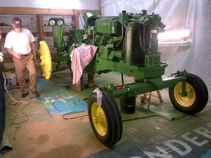
Thanks for Tx Jim and John T's comments. We got the tractor started tonight. First time it has run in 3 years. After a couple minutes the dash light went out. Guess it took the generator brushes a few minutes to get the dust off the commutator and start throwing a voltage. Here's a picture just before we put the rear tires on and started it up.
We started looking at the old light, and it was exactly as you stated with 2 wires, one to the bottom of the bulb and the other to the base of the bulb. We had to get creative and figure out a way to isolate the light housing from the tractor dash but once we did this, the light only comes on with switch.
Thanks for Tx Jim and John T's comments. We got the tractor started tonight. First time it has run in 3 years. After a couple minutes the dash light went out. Guess it took the generator brushes a few minutes to get the dust off the commutator and start throwing a voltage. Here's a picture just before we put the rear tires on and started it up.
Similar threads
- Replies
- 23
- Views
- 962
- Replies
- 5
- Views
- 143
We sell tractor parts! We have the parts you need to repair your tractor - the right parts. Our low prices and years of research make us your best choice when you need parts. Shop Online Today.
Copyright © 1997-2024 Yesterday's Tractor Co.
All Rights Reserved. Reproduction of any part of this website, including design and content, without written permission is strictly prohibited. Trade Marks and Trade Names contained and used in this Website are those of others, and are used in this Website in a descriptive sense to refer to the products of others. Use of this Web site constitutes acceptance of our User Agreement and Privacy Policy TRADEMARK DISCLAIMER: Tradenames and Trademarks referred to within Yesterday's Tractor Co. products and within the Yesterday's Tractor Co. websites are the property of their respective trademark holders. None of these trademark holders are affiliated with Yesterday's Tractor Co., our products, or our website nor are we sponsored by them. John Deere and its logos are the registered trademarks of the John Deere Corporation. Agco, Agco Allis, White, Massey Ferguson and their logos are the registered trademarks of AGCO Corporation. Case, Case-IH, Farmall, International Harvester, New Holland and their logos are registered trademarks of CNH Global N.V.
Yesterday's Tractors - Antique Tractor Headquarters
Website Accessibility Policy