Wiring Schematic for JD-60 Generator

EScottUtz

Member
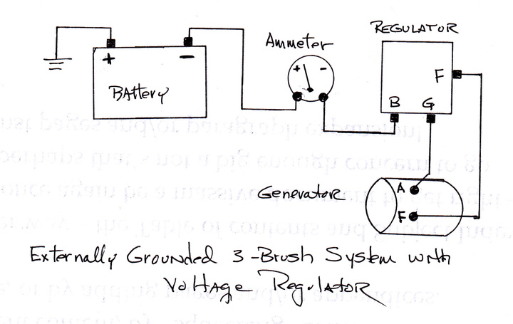
Does anyone out there have a wiring schematic for a JD-60 that they would share with me? I need to know where the wires go on the generator & regulator. I have 3 posts on the regulator and 2 posts on the generator. I think that there are 2 wires that go back to the dash. Thanks.
 
I dont think the diagram has the VR labels, so

BAT on VR up to ammeter on dash
FLD on VR to gennys FLD post
ARM/GEN on VR to gennys ARM post

Just to be safe once wired but BEFORE starting, Id Polarize the genny. That tractor was originally Positive grounded remember.

John T
 
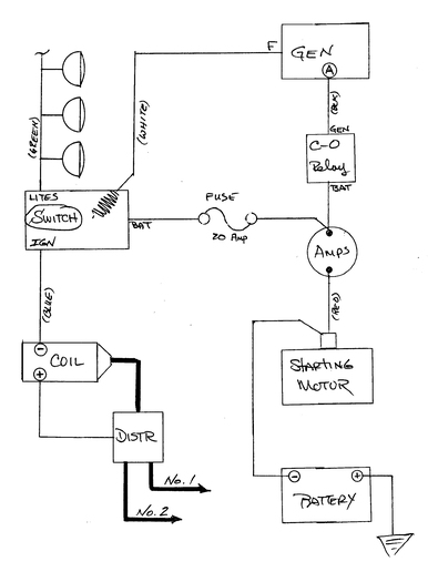
Yes John, the wiring diagrams from manuafacturers are much too cryptive at times. Here is a dwg I found elsewhere on this site some time back - looks like it should apply here. I really need to fancy it up some - ah but later! (PatB)
a21526.jpg
 
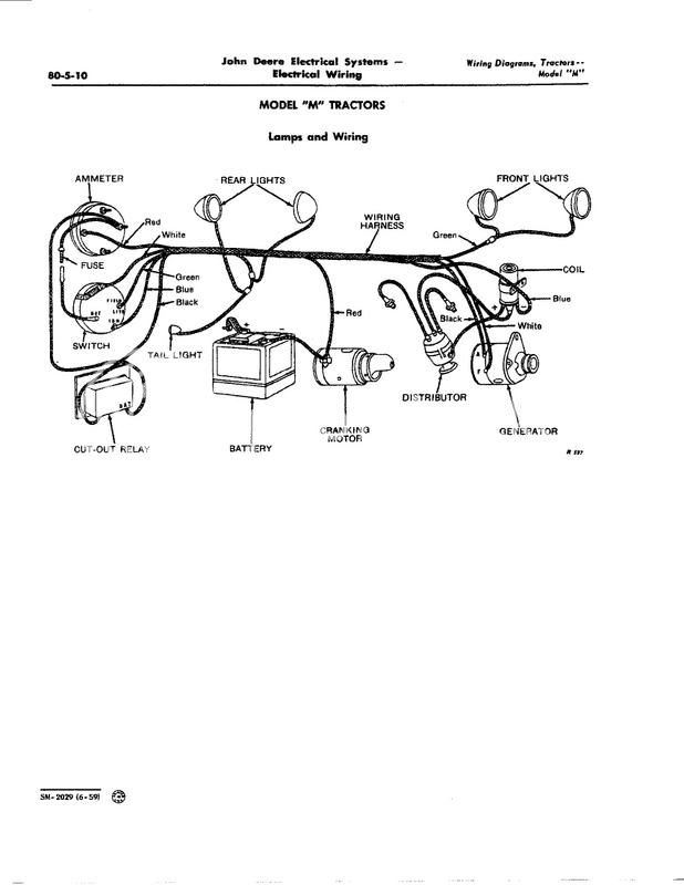
Yep, Those SM 2029 diagrams sure arent perfect ESPECIALLY where they lump so many different models altoghether but, like you, its about all I have to offer usually. I'm pretty sure their model M diagram has errors but I cant take the time to do them all correct. Here on the net theres only so much we can do and so much time. Thats why I dont even think about instructing people how to adjust a VR lol

GET WELL

John T
 
Thanks Pat for the info. I found what I needed on your web web site. I knew I had seen it somewhere, but couldn't remember where. That drawing you put up here is great. Thanks.
 
Hi John - Yes, I agree. Sometimes there is an added invitation to delve in a bit more, but the number of variables makes general discussion hazardous! This is especially true for battery charging systems. That's is unfortunate too because as time passes, a good deal of the "old-time" information is being diluted and/or washed down the drain.

On the issue of the JD-M wiring diagram, here is one I have been kicking around for a spell. I haven't posted it on my site yet - for a number of reasons I guess. Time is one - as it is for you. Check it out some - if you think it is worthy, I will post a cleaned up version. (PatB)
a21528.jpg
 
Looks pretty good, I think theres some confusion (on the SM 2029) regarding the back of an actual switch, (no access to an M handy here)

1) Theres a single actual visible external wirewound resistor on back of an M switch correct ???

2) Is such a resistor the Field current limiter resistor orrrrrrrr the light dimming resistor?? (Field current I'd say, not sure if M even used a dim lights position or not)

Your drawing indicates is the Field resistor AND SO DOES THE SM 2029 DRAWING its just that on SM 2029 it looks like it says FIELD where the light wire attaches???

I kind of think your drawing is more accurate then SM 2029. NOTE on IHC switches with two external resistors, the heavy wire coil is light dimming and the smaller wire wound on a flat rectangle is the Field resistor because the light dimmer (big wire coil) requires much mower power (heat dissipation) then the Field current resistor. HOWEVER Im unsure the M even had a DIM position becasue if they did TWO RESISTORS WOULD BE REQUIRED

I think your drawing is better becasue the SM 2029 mis labels FIELD

John T
M-1-JPEG.jpg
 

We sell tractor parts! We have the parts you need to repair your tractor - the right parts. Our low prices and years of research make us your best choice when you need parts. Shop Online Today.

Back
Top