More re: 3-brush gen wiring

John T and others - thanks for the input. For the last 15 yrs I have wired the field to the adj brush, with varying success, based on a sketch I did from a dis-assembled gen. I am working on a JD "M", and the gen didn't work with that hook-up, so I connected the "A" to the adj brush, and the gen went to work. ????? Then I went back to my MT and re-wired it, but it doesn't work either way, even tho the internals ohm out properly. None of my gens pass the "motor" test, in that they motor, but the speed doesn't increase when the field is un-grounded. ????? Any suggestions?
 
the field wire has to go to the third brush.for max output hook field wire up along with the a term&grd the f term.a good gen will produce its max.
 
Usually if she motors just fine (field grounded or not) that tells me basically the Armature and Brushes are good PROVIDED she motors fast n smooth n even RPM. (still could be an armature problem which takes a growler as Bob noted)

Next if you motor it with the field dead grounded to case frame but she DOES NOT speed up a bit when you unground the Fields, then I suspect a field problem which can cause her to NOT charge.

Typical Field problems may be one of the coils is shorted out to case somewhere,,,,,,,,its shorted to case (or broke open) where the 2 fields splice in the middle,,,,,,,,,,the Field terminal post has been overtightened making the Field ALWAYS grounded and she would always be in max high charge,,,,,,,,,,shes overtightened and the field wire is broke off from the terminal (non charging and no PRM motor speed change),,,,,,,One of the fields is OPEN

If you ohms out the fields, Id expect maybe 3 to 6 ohms or so (for the 2 in series), if zero theres a field short, if open its open and bad. Obviously the fields termination must be present at the FLD post while their beginning is at the third asjustable/moveable brush

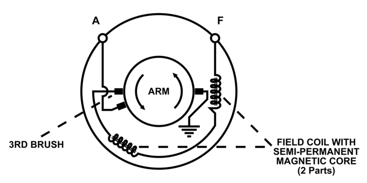
Id say a genny can still charge if you swap the brush wiring, but I still (until proven otherwise) stand on my earlier (and Bob agrees) post that the MAIN FIXED NON GROUNDED BRUSH is what attaches to the ARM post (other main brush is grounded) while the beginning of the Fields is what wires to the third adjustable/moveable brush. That way you increase field current for more output if the third brush is close to the main fixed brush while the gennys output is across the commutator at 180 from the other main grounded brush.

I think you have a field problem (shorted or open) and the main fixed brush is what wires to teh ARM post buttttttttttttt its your tractor n youre free to wire it as you please.

I agree with Bob the best way to test the armature is with a growler as my Motor test is still just a shadetree mechanics approach NOT perfect

let us know

Of course if Im wrong and the ARM wires to the adjustable third brush I will eat humble pie but I may not like it lol, Im never too old to learn. Again I say it can still work that way however

John T
 
Have you found on the 3rd brush genny that you get sparks with the brush to full power? I have a 47 G that does it. If I back off a little no sparks. ??? Gen has a regulator on it.
 
I think some of that may have to do with the third brush is only supposed to be so close the the main fixed brush (NOT as far close as possible). Some delcos say to maintain at least 1 1/2 commutator segments of separation while others are 2 1/2.

John T (PS Im NOT a genny repair shop, sure I fix my own and am knee deep in theory, but lack the expertise of a guy who fixes them for a living)
 
Sometimes a couple of simple drawings and the wording to accompany them will go a long way toward setting the system up in a person's mind.

The first diagram is a typical John Deere 6-volt externally ground system (Fig 701) and the second a basic diagram for a 3rd brush generator (Fig 702).

What follows is an excerpt from the John Deere Model "H" Restoration Guide, Chapter 7. (PatB)
-------------
GENERATOR OUTPUT CONTROL CIRCUIT

Field Current – (Ref Figures 701 and 702) -- It is the strength of the magnetic field in which the generator's armature is rotating that controls armature current at the generator (A), the output terminal. The strength of the magnetic field is dependent on field current rate. And field current is a function of how much resistance to current flow is placed in series with the field coil windings. The "H" tractor uses an externally grounded, third-brush generator system.

When the armature rotates, voltage is developed at the third brush. Current then flows from the third brush, through the two field coils, out of the generator case via the field (F) terminal, and ultimately to ground through the "light and generator charging rate control switch" (Generator Output Control in Fig. 701). A direct short to ground of the field terminal will result in a high field current (high-charge) while a return to ground through a resistance will result in lowered field current (normal operation). At essence here is the three-position Resistor Light Switch and in which the position the operator has it. This type of light switch is typical on early farm tractors to perform two functions. One is to allow the operator to select a higher charge rate when the battery charge is too low for satisfactory operation, and the other to switch battery power to illuminate the lights while maintaining the high generator output rate. The charge control function of the resistor light switch makes it a central element of concern when troubleshooting a non-charging system.

Worthy of mention is a warning from your Operator's Manual: If at any time you find it necessary to operate the tractor without the battery, remove the field wire from the generator terminal marked "F" on the generator frame or slip off the generator belt and wire it back against the fan shaft. If the generator is run without the battery, excessive voltage will build up in the generator causing damage to the generator's field coil windings. ++++
a20591.jpg

a20592.jpg
 
GREAT info, Thanks Pat,

THAT AGREES (BOTH in text and drawing) WITH WHAT MYSLEF AND BOB THOUGHT (I just couldnt envision the ARM post wiring to the third moveable brush). The main fixed (non grounded) brush attaches to the external ARM Post while the third adjustable brush wires to the Fields. Same as the drawing in the YT MAG article its NOT showing the main fixed exactly 180 opposite from the main grounded brush WHICH I STILL THINK IS CORRECT BUTTTTTTTTTTTTTTT if you notice NEITHER does it show ther fields 180 opposite across from each other WHICH THEY INDEED ARE

Thats my story n Ima stickin to it. ARM WIRES TO FIXED MAIN NON GROUNDED BRUSH,,,FIELD WIRES TO THIRD ADJUSTABLE BRUSH

Fun discussion, for us sparkies at least lol

John T
 
Yes, oh yes! The geometry MATTERS! By switching the 3rd brush to the "A" terminal, we now have what I think will be a partial disconnect. The output brush terminal and the ground terminal MUST be 180° from each other. (PatB)
 
RIGHT ON its just intuitive common sense the gennys outout is between the fixed ARM brush and Grounded brushes and its best they are 180 opposite each other which also relates to commutator segments and their wiring. Seems none of us had a real accurate drawing however lol

Fun chat

John T
 

We sell tractor parts! We have the parts you need to repair your tractor - the right parts. Our low prices and years of research make us your best choice when you need parts. Shop Online Today.

Back
Top