So I split my 3600 because a freeze plug rotted out.
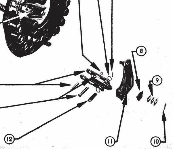
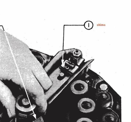
I noticed a cotter pin on one of the arms was gone, but no other damage. Decided to service the clutch and other parts in the bell to see if it possible to die before I ever have to split a tractor in the summer in Georgia again. I had no trans or PTO problem previously, but some glazing was evident, the bell was covered in black gunk so rear seal was leaking. Even found old shims in there too.
I have the B&B type II IPTO clutch out and on the bench. Marked it up for reassembly and took it apart with c-clamps and inspected everything. I'm putting clutch back together and I have questions.
1. The flange on the PTO disk was facing the trans. Is this correct for 3600?
2. I know Arms to Flange is 2.110, but I noticed shims on every arm. They were installed over the arm between the arm and clip and not down on the fulcrum. Makes no sense. Is this right?
3. Should I take the PP to a dealer or clutch shop to set? Or can I mount it to the fly wheel and use a runout gauge to check/adjust the fingers/finger bolts? Between the shims and the adjustment nut, how complex can it be?
Thanks - $1 part = full split but glad I saw what was going on.