Tony Wells
New User
I have a TW-35 Ford, built in Belgium, tractor in the shop. It is equipped with the electronic dash. Somehow, over the years, some electrical issues have cropped up and someone switched to a Murphy gauge setup, but now, I get all the warning lights and audible alarms when running. Additionally, the fuel cutoff solenoid must be jumped to a 12 V to even run. The harness and four main interconnecting plugs are all clean and still have factory dielectric gel in them so not really suspecting them (yet). The machine will start and operate normally but for all the warnings.
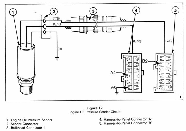
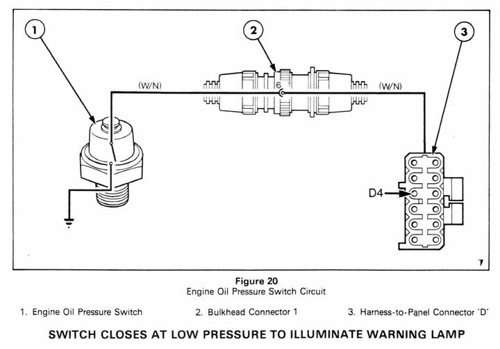
There is a lot of wiring that has crispy insulation. Ford/New Holland must have chosen incorrect insulation material. It has not aged well, even though this is a 1997 model. I really would like a full schematic, but that's a long shot I imagine. At this point, my focus is on the oil pressure switch/sending unit. The manual from the dealer is only a Clymer (Haynes), and does not have much detail regarding wiring specifics. Some of the crispy insulation has resulted in wires breaking (plus some questionable repairs). It has been painted, so I had to get back in the loom a ways to get the colors of the wires to the sending unit. The book I have shows separate switches for the light and the actual gauge. This machine however, doesn't seem to have the forward mounted switch. The main sending unit is a 3 wire, but the bundle coming towards it has 4 wires. The patchwork repairs have left the colors at the sending unit a bit mysterious. About all I can be sure of is that one is red, but the harness leading to it has no red wires. I suspect there may have been a translation at a connector, which has been done away with in favor of twisted wires and tape. With 2 wires fatigued and broken, I'm a bit lost to reconnect it, and see if it is even good. It has no short to ground, but I think one wire should be grounded when not running, thus turning on the warning light. The other wire I believe is the actual gauge wire, but I'm not sure.
Can anyone shed some light on this? This tractor has no SN plate, at least where it is supposed to be, so I cannot provide that, but the engine part number and serial I do have.
Engine PN: FNH9673623 DS
Eng SN: 6522308
Build date 10-28-97
A schematic would be ideal, but an explanation of the 4 wires on a 3 wire sending unit would go a long way.
Many thanks in advance!
Tony Wells (First post)