No Timimg Marks O Flywheel.

Taking the injection pimp off a TW35. I posted this about 2 months ago. Finally getting around to doing this. I had a new flywheel put on 2 years ago. Evidently there are no timing marks on the new one. I took the valve cover off and got the engine close to top dead center. I then lined the timing marks up on the injection pump and removed it. Will I be ok to install the pump back like this?
 

If you took the pump off with timing marks lined up and put it back on the same way you should be good to go. That's the way I do diesel pumps.
 
That should work if you're careful not to move the engine while the pump is out, although it wouldn't be close enough for me. That must not be an OEM flywheel if there are no marks on it.
 
Are you CERTAIN that there are no marks on the flywheel? I can't imagine even an aftermarket part not having them. If your pump were removed just anywhere, you'd be dead in the water with no marks.

If indeed there are no marks on the flywheel, and if this is my machine, then I'm making my own marks. I'd start by finding approximate TDC on #1 by watching the valves. I'd then back the engine up by about 20 degrees. I would then drop a valve into #1 cylinder and anchor it in place. I would then turn the engine over until the piston hits the valve, and mark the flywheel. I would then turn the engine over the other way until the piston again hits the valve, and again mark the flywheel. I would then split the distance between the two marks, and this would be exact TDC.

I would then measure the circumference of the flywheel and calculate how many inches per degree, and then make an appropriate mark for 25 degrees BTDC, which I believe is the timing spec for a TW.

Note: This is all easier said than done,and is MUCH easier with the engine out of the tractor. In fact, if the engine were out of the tractor, I'd have a degree wheel on the front pulley. Most people would not go through this kind of effort to get it right, but I would. I did it on my 6000 to verify that the marks on the front pulley were correct. I consider myself a stickler for accuracy. Trial and error does not even cross my mind.

Below is a picture of how I did it on my 6000. The degree wheel is on the flywheel, because the factory marks are on the front pulley (this is backwards of how I'd do it on a TW, or most any other Ford for that matter). You can see the plate bolted to the top of the block that has a bolt protruding through it for a piston stop.

The main reason I did this is because the timing marks on the 6000 are on the outer dampner of the front pulley, which is rubber mounted to the inner part of the pulley. I wanted to be sure that the rubber did not slip, which can and does happen. If the rubber slips, and you don't know about it, you have a poor running engine at best.
cvphoto33303.jpg
 
I agree 100% with getting the timing right! I turned the motor by hand searching for the timing marks and found none. I then turned the motor till #1 intake started closing, kept turning till it stopped and the rocker arm was "loose", then lined the pump timing marks up and removed the pump. With the pump marks lined up, I again searched for timing marks and found none. After, I put the pump back on, I'll again look for marks. I don't dare move the motor now. I did make some marks myself so as to get the pump back in the same place. We had a 272 Ford motor in a truck once upon a time that the front pulley was for another motor. It can be a nightmare for sure. Thanks Bern!!
 

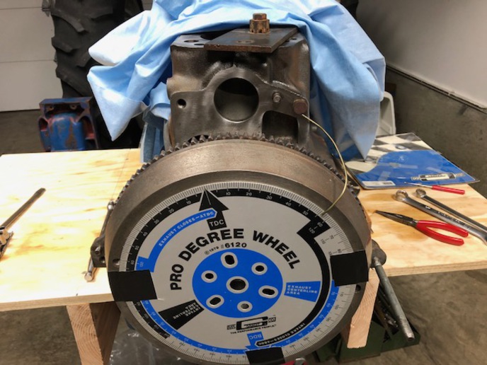
There are plenty of ways to find TDC this is what I like to do... You could put you indicator on an exhaust are intake valve while its on overlap (On The Rock). I have used this to confirm valve timing 100's of times I have used this when no timing marks were to be found are in question.

https://forums.yesterdaystractors.com/viewtopic.php?t=1399069&highlight=rock

If you could set up two dial indicators one on intake ans one on the exhaust you could nail it dead nuts...

I am applying this to a Ford Flathead for reference...

Let me state this so you wan't think I am dreaming it up...
A old mechanic/machine shop operator, X sailor born again christian, Dragon slayer once told me...

An old trick to see if valve timing is right on a flat head would be to remove the head or lifter cover and bring #1 cyl up to compression stroke. While you are rotating the engine coming up on #1 TDC, #4 should be on overlap (exhaust valve closing, intake valve opening). This should happen right on TDC #1. If a valve on #4 is wide open or doing nothing at all, the valve timing is off... weather it's the cam gear . crank, gear or key way, broken cam,etc. The reason # 4 is the cyl in question is because that is the "middle" are Companion cyl in the firing order 1-2-4-3. The "middle cyl should always be in overlap. for instance, on a chevy the firing order is 1-8-4-3-6-5-7-2, so if we wanted to see if the valve timing was off we would look at cyl# 6 to see if it was on overlap rolling the engine over to #1 TDC. It should overlap right at #1 TDC at 0 degrees

Master this and you will never b stumped again timing a engine,,, On all n's I have seen the when the marks line up the piston will B at haft way of it travel and the crank throw at 90 deg,,, you will c this on some older Ford engines and some newer GM engines,,, its has been said that it makes for easier assy cuzz this is the location were the cam is less loaded by the valve springs,,, well theirs no load on 4 lobes at this time 4 sure

Take the time now to play with this and never B stumped again on any engine,,, The Flathead gives you the ability to c the piston valve relationship better than any engine I know of...
 
Your method with indicating valve movement is fine for checking valve timing, where being a tooth off can
throw the timing off several degrees, but it's not close enough for injection timing. Pump timing ideally
should be set at the factory spec +/- 1 degree, and there's simply no way you're going to find TDC
accurately enough by watching the valves, with or without dial indicators.

Your method also assumes that split overlap occurs at exact TDC, and while that's usually the case with many
engines, it's not true for all. Take a diesel Ford 5000 as an example, the intake opens at 10 degrees BTDC, and the exhaust closes at 7 degrees ATDC. Also note the 10 degree difference between diesel and gas. Sorry, your method would not be "dead nuts" with regards to finding TDC.
cvphoto33333.jpg
 

That's why I added two indicators normally a gas engine is 5 and 5 on a gasser a degree are two is not going to mater.

I will leave the diesel to you :)
 
Where am I going wrong here?
I cant see any way of finding TDC by using the valves. Why cant you put a dial indicator down #1 injector hole?
 

The way I have always found TDC is on a gas engine, which can be done the same with a diesel. Is to pull #1 plug, and use a old plug, then break the porcelain out, and tap it, and put a piece of threaded rod into it, with a jam nut on it. I set the tip just deep enough to stop the piston from going over the top. I bring the piston around to it, by HAND till it stops. Mark the crank/pulley. Now rotate the crank the opposite way till it stops again, then mark it again. The center of the two marks IS TDC.

Just use a old injector or anything that will screw into the

Simple to do! No guessing, Accurate!

injector hole.

Pat
 
You can use the valves if you assume that valve overlap is at exact split overlap, which means that both intake and exhaust valves are open the exact same amount at TDC. However, as I said earlier, this method is not accurate enough for me. For one, it does not take into consideration any wear in the timing gear train.

Your method, which puts an indicator down an injector hole (using some sort of an extension), would actually be more accurate than using the valve overlap method. However, it is also not close enough for me, because there is about 3-4 degrees of crank movement at TDC where you have no piston movement. In other words, the point at which the piston stops moving is not exact TDC.
 
You do it the same way I do, except that I use a valve for a piston stop and not something through the
injector hole. The reason for this is that most of the engines I'm doing this on are IDI engines that have
pre-cups in the heads, which are pretty much all of your Japanese engines. This means you can't go through
the injector hole.

Some Japanese diesels have no timing marks; injection timing is specified solely in inches or mm of piston
travel.
 
(quoted from post at 14:44:51 08/13/19) I would then drop a valve into #1 cylinder and anchor it in place. I would then turn the engine over until the piston hits the valve, and mark the flywheel. I would then turn the engine over the other way until the piston again hits the valve, and again mark the flywheel. I would then split the distance between the two marks, and this would be exact TDC.


Is not what I said the same as what you said? But you say my way isn't close enough for you???

I'm confused!

I have built engines all my life, and I have built more then I could think of remembering, I started in '63 with my older brother (not including all my 2 stroke & 4 stroke nitromethane diesels) and your the first person I have ever heard say it's not close enough. In fact it's exact TDC.

Pat
 
You evidently misunderstood me. What I said was that both of our methods are accurate, it's just that I use
a valve for a piston stop, while you use something through the injector hole. The reason I don't go through
the injector hole is because you can't on an IDI engine, which would be the majority of your Japanese
diesels.
 

We sell tractor parts! We have the parts you need to repair your tractor - the right parts. Our low prices and years of research make us your best choice when you need parts. Shop Online Today.

Back
Top