
Well I finished removing, cleaning and reinstalling the control valve for my 5000 SoS. I wanted to say THANKS to those who helped with the questions, and to post what I found when I did this.
I must say having a digital camera when doing something like this was very helpful. It was nice to have the before pictures to refer to in order to get it back together right.
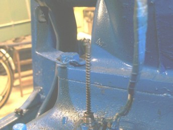
This first picture shows the upper half of the gear selector/cable removed. I was going to try removing the control valve without doing so, but then decided to remove it and was glad I did. I would not have gotten the control valve out without removing the selector/upper cable since it allows you to slide the cable up out of the conduit so you can twist and separate the upper and lower cables.
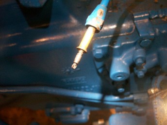
The second picture shows the end of the upper half. If you look close, you can see how it twists together with the lower half and is held together by the conduit.
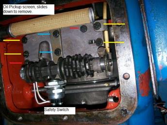
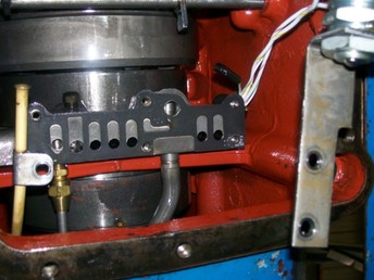
The third picture shows the control valve prior to removing with some notations. The oil pickup screen rotates slightly and can be slid down and out.
The yellow lines show the bolts that need to be removed to remove the control valve assembly. The blue lines also have to be removed to get the assembly out but are shown differently since they hold the safety switch. The manual suggests removing the wires to the safety switch, but I couldn't get a screw driver in there. I thought if I could loosen the control valve assembly, it would drop down enough to get at the screws. When I dropped it down, I just slid out the bracket and left it hang.
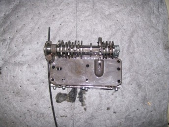
The fourth picture shows the control valve assembly removed. It shows the bottom of the assembly as it would appear when installed.
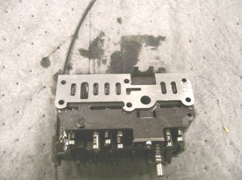
Picture 5 shows the top side of the control valve, and the various valve spools installed. This picture came in very handy since when I separated the two, the spool valves rotated off the cam followers and I couldn't tell which way they were supposed to face. When putting it back together, the slots on the valves had to be facing the right direction to be installed properly. If you look at the bottom of the picture, all the valve slots face left, except for the one on the extreme left, which faces right.
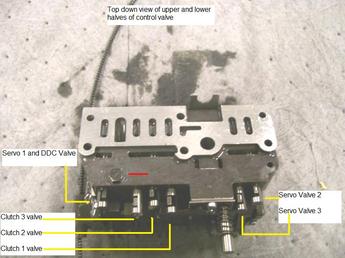
Picture 6 is the same as 5 but with notations showing which valve is which. If you right click the picture and save it to your computer, you can zoom in to better see the notations and valves.
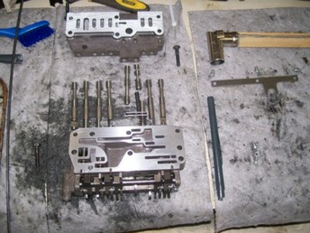
Picture 7 shows the upper and lower halves separated with the spool valves removed for cleaning/polishing. I used 400 grit sandpaper and kerosene as a solvent. The blue tube on the right is a roll of sandpaper used to clean/polish the bores. The valves slid in and out much easier after some light polishing.
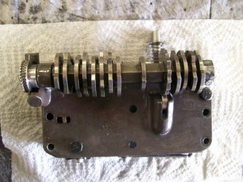
Picture 8 shows the assembly put back together ready to be put back in. Note the two bolt heads. These are only used to hold the two halves together, along with one other bolt on the other side.
Picture 9 shows the transmission with the control valve removed. The old gasket is still in. The yellow tube on the left is the conduit for the selector cable.
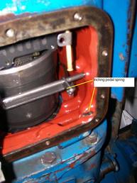
Picture 10 shows where the inching pedal spring is supposed to be. Mine was missing when I bought the tractor since it had broken and the previous owner removed it. I bought a spring at a farm supply store and installed it. The spring along with polished valves certainly make for a better operation. The tractor shifts nice, and I can feather it now. Before, there was no inching/feathering. It was either full go or stop.
Thanks to all who helped with questions. Hopefully this helps someone.
I must say having a digital camera when doing something like this was very helpful. It was nice to have the before pictures to refer to in order to get it back together right.
This first picture shows the upper half of the gear selector/cable removed. I was going to try removing the control valve without doing so, but then decided to remove it and was glad I did. I would not have gotten the control valve out without removing the selector/upper cable since it allows you to slide the cable up out of the conduit so you can twist and separate the upper and lower cables.
The second picture shows the end of the upper half. If you look close, you can see how it twists together with the lower half and is held together by the conduit.
The third picture shows the control valve prior to removing with some notations. The oil pickup screen rotates slightly and can be slid down and out.
The yellow lines show the bolts that need to be removed to remove the control valve assembly. The blue lines also have to be removed to get the assembly out but are shown differently since they hold the safety switch. The manual suggests removing the wires to the safety switch, but I couldn't get a screw driver in there. I thought if I could loosen the control valve assembly, it would drop down enough to get at the screws. When I dropped it down, I just slid out the bracket and left it hang.
The fourth picture shows the control valve assembly removed. It shows the bottom of the assembly as it would appear when installed.
Picture 5 shows the top side of the control valve, and the various valve spools installed. This picture came in very handy since when I separated the two, the spool valves rotated off the cam followers and I couldn't tell which way they were supposed to face. When putting it back together, the slots on the valves had to be facing the right direction to be installed properly. If you look at the bottom of the picture, all the valve slots face left, except for the one on the extreme left, which faces right.
Picture 6 is the same as 5 but with notations showing which valve is which. If you right click the picture and save it to your computer, you can zoom in to better see the notations and valves.
Picture 7 shows the upper and lower halves separated with the spool valves removed for cleaning/polishing. I used 400 grit sandpaper and kerosene as a solvent. The blue tube on the right is a roll of sandpaper used to clean/polish the bores. The valves slid in and out much easier after some light polishing.
Picture 8 shows the assembly put back together ready to be put back in. Note the two bolt heads. These are only used to hold the two halves together, along with one other bolt on the other side.
Picture 9 shows the transmission with the control valve removed. The old gasket is still in. The yellow tube on the left is the conduit for the selector cable.
Picture 10 shows where the inching pedal spring is supposed to be. Mine was missing when I bought the tractor since it had broken and the previous owner removed it. I bought a spring at a farm supply store and installed it. The spring along with polished valves certainly make for a better operation. The tractor shifts nice, and I can feather it now. Before, there was no inching/feathering. It was either full go or stop.
Thanks to all who helped with questions. Hopefully this helps someone.