Wiring to Ignition Switch

equeen

Member
Thanks to folks here, the voltmeter is now working on the TEA 20 Ferguson. Would be delighted to have more wiring help and confirmation.

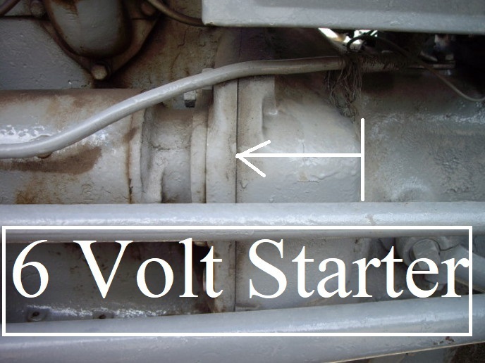
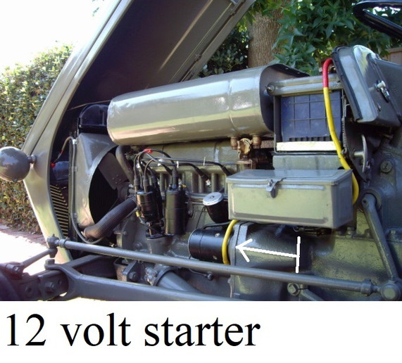
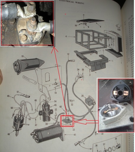
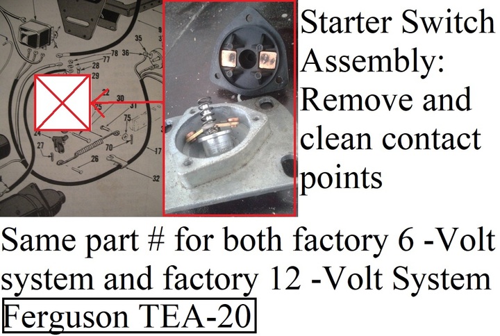
The tractor has an unused gearshift starter switch. Not ready to dig into it. Tractor has 12v battery, alternator, coil and whatever.

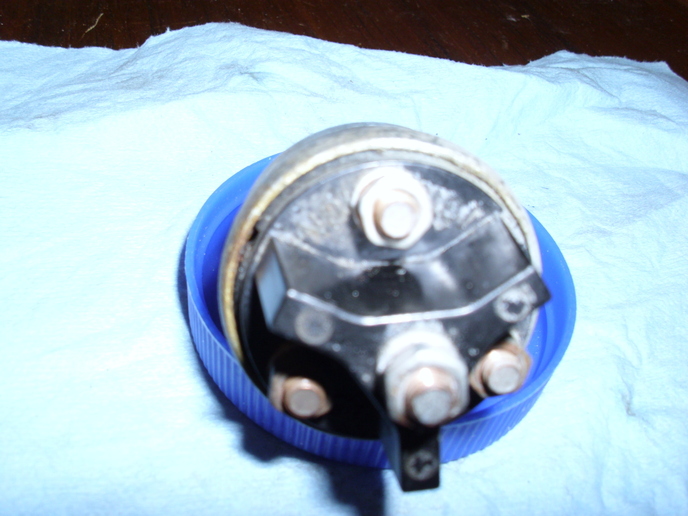
I'd like to dig into the ignition switch which has 4 posts:
Bat....
Acc....
Ign....
Center post not named

Which wires from where should be going to each post on the ignition switch???

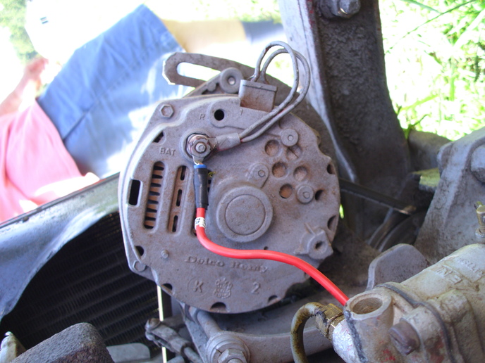
I'm also interested in knowing for sure where the bat alternator wire goes?

Please toss me a rope and pull me to safety. Thanks.
 
4 position key switch is. . . (1)Off (2)ignition (3)ignition and lights (4)lights
Wired accordingly.
Batt to Battery
Acc to lights
Ign to ballast resistor/coil
4th post? Continuity checks to what position?
 
Does the center one have an S by it?? If it does that is the start as in it hooks to a solenoid to spin the starter over to start it up
 
The armature wire from the alternator should go right to the battery either directly or to the post on the solenoid that the battery cable goes to. If you still had an ammeter it would have gone there first.
 

cvphoto94738.jpg


If this works, there is a photo of the ignition switch. 3 posts evenly spaced around the switch and the 4th post in the center, elevated from the others. The three posts are labeled BAT, IGN, ACC. There is no label I can find anywhere for the center, elevated, post.

Now, I have wired the center post wire to the little s post on the starter solenoid. I have nothing wired to the neighboring little I post on the starter solenoid.
I will stop now so as not to confuse anyone. It doesn't really matter how this WAS wired or IS wired because it wasn't working for the man who had it before and I will not get it running for quite some time. I just want to get the wiring correct for now. I've put new wires on it and numbered them, so I know what goes where. I also know that the engine cranks - but doesn't start - the way I had/have it wired and due to other reasons including no points in distributor. Also have fire to + side of coil wih ignition on.

So, what goes where - properly?
 

Bruce(OR) was describing the post functions on a different switch than the one you have in your picture.

You are correct with the raised center terminal (which is the start terminal) wired to the S terminal on the solenoid. The I terminal of the solenoid will only have a wire on it if it is used to bypass a ballast resistor, located ahead of the coil, to provide full voltage to the coil during starting. The Battery terminal will get a wire from the post on the solenoid the battery cable connects to. The IGN (ignition) terminal receives the wire going to the coil and any thing else you want to turn on and be live when the key is in the run position. Anything you connect to the ACC (accessory) terminal will be live both when the key is in the run position and when it is turned to the accessory position.

As you get further along the wiring to your alternator will come into play and, depending on the alternator, can affect the ignition if not done right.
 
I've just tested the ACC post - which, for now, has nothing permanently wired to it. I put a temporary wire from it to an old siren I have and it works whether or not the ignition switch is on. Just the way I want lights wired.

Now, if the neighbors and their dogs will just calm down.

Thanks to the help from folks on this forum, I am now finished with the wiring business until after I learn more about the tractor and get some other things taken care of, such as identifying proper Ignition kit for a late Lucas distributor
 
Thanks John Deere D.
I have a copy of what appears to be that Service Manual through Section J. I did see some electrical schematics: one for a 6 volt system with a voltage regulator, another for a 12v diesel with control box (i.e. voltage regulator, I think). Neither were very helpful and neither was the same colored diagram that you've posted here and that I've seen elsewhere. Even this schematic/diagram does not fit my need. It appears to have a generator and voltage regulator, among other weaknesses regarding what I needed. However, I'm confident that it will be helpful to others with needs that fit.

Another project is coming up and I would welcome your guidance: looking into how the S (start) on the trans cover and the two post device under the battery box should work. This is discussed to some degree in pgs G23-27 in my Ferguson Service Manual; however I'm confused right off the bat. My manual on pg G23 mentions 3 wires connected to the switch and mine only has 2 posts (both without wires for many years as the paint on them reveals). My first question is: May I remove the 4 bolts holding the switch down and lift up the switch just to take a peek for now, then put it back without damaging anything?

Thanks
Gene
 
As for changing the wiring schematic of the colored drawing to match your alternator, you need to identify the alternator. Different alternators require different wiring, some even require an external regulator. If you don't know what it is post a couple pictures of it, being sure to show all the terminals, and someone will identify it for you.
 

cvphoto94783.jpg


Photo is presented upside down to get a reading of K 2, if that is significant. It's a Delco. Red wire connected to Bat terminal on alternator.
 
Here's the way It should be wired. Except you don't have a tach stud making it only for two little wires to hook up.


mvphoto78669.jpg


This post was edited by J.Wondergem on 07/17/2021 at 07:28 am.
 
Quote:
Another project is coming up and I would welcome your guidance: looking into how the S (start) on the trans cover and the two post device under the battery box should work. This is discussed to some degree in pgs G23-27 in my Ferguson Service Manual; however I'm confused right off the bat. My manual on pg G23 mentions 3 wires connected to the switch and mine only has 2 posts (both without wires for many years as the paint on them reveals). My first question is: May I remove the 4 bolts holding the switch down and lift up the switch just to take a peek for now, then put it back without damaging anything?

Thanks
Gene

Bob...

cvphoto94951.jpg


cvphoto94952.jpg
 
Thank you sir!

I've just opened it up and cleaned up the terribly corroded copper a bit.

Have also looked down inside while moving the gearshift lever and see a rod rotating a bit down in there.

It may well be that someone just didn't like starting the tractor with the gearshift lever.
 

We sell tractor parts! We have the parts you need to repair your tractor - the right parts. Our low prices and years of research make us your best choice when you need parts. Shop Online Today.

Back
Top