Janicholson - thanks - alternator pic - 400 gas

55 50 Ron

Well-known Member
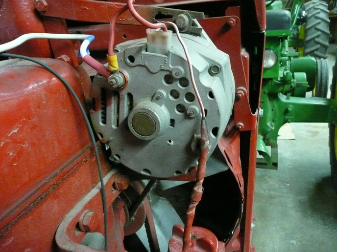
Here's a photo of the alternator. I couldn't see any identification - but didn't look anywhere I couldn't see without moving it.

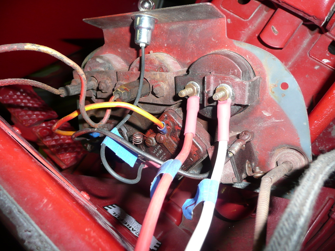
I finished a "rough-in" of the new wire harness. Everything works except I need to change the ammeter wires around - one of those things that are easy to get connected wrong.

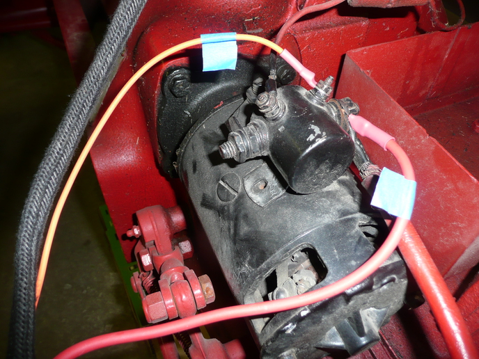
What resistance should be measured between the two small terminals on the starter solenoid?
Also between the battery terminal and the "start" small terminal?
I was a bit puzzled by what I measured (7.2 ohms and 4.8k ohms respectively), but since everything works, those resistances must be at least close.

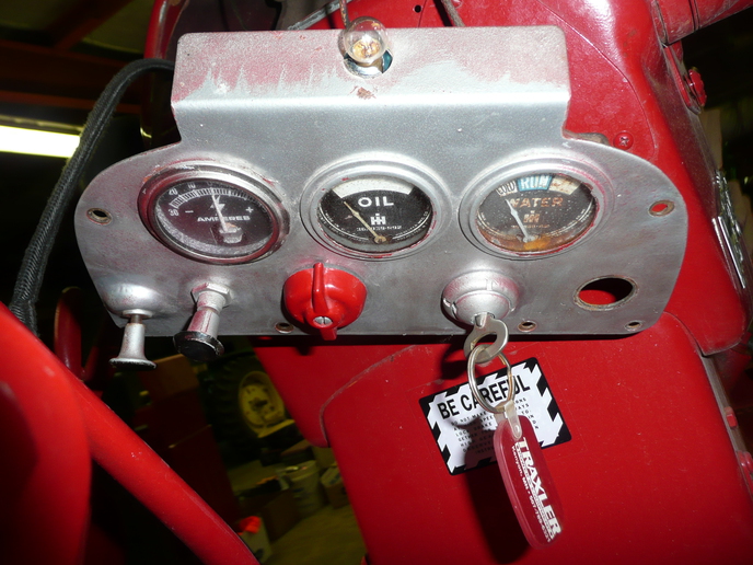
Solenoid photo also attached plus a couple
(front and back) of the dash panel.

I'll be "neating up" the harness - just wanted to see if it all worked first.
SORRY FOR DUPLICATE PHOTOS
a87207.jpg

a87208.jpg

a87209.jpg

a87208.jpg

a87209.jpg

a87208.jpg

a87207.jpg

a87210.jpg
 
That looks just like the Delco 10SI alternators that I have on my H and 300. I don't know how to tell for sure though.
Zach
 
if the alt is like most delco single wire alt, terminal 2 doesn't need to be hooked up.if you do use terminal 2 , it needs to be switched hot and it will start charging without revving the motor up.wired the way it is now i think it will drain the battery. ter 1 is for indicator light
 
But it's not a single wire alternator, it's a 3 wire alternator as you can see from the photo. All I did was install a new wire harness, I didn't modify the electrical connection points and it worked previously until the old harness deteriorated and it works after new harness installation.
 
The alt is an SI series, as wired it will be fine (reversing the amp gauge is better than getting used to seeing it work backwards)
The starter relay is wired with the S small terminal going through the activation coil inside then to ground (mounting bracket), 7 ohms is about right. It is the source of magnetism that moves the plunger and pushes a copper disk against three contacts, connecting them together as long as the S is energized. The big terminal to the battery is the source of electricity to the disk. The other big contact (now connected) is supplying the starter with high current energy. The last contact is smaller, it is connected to the I terminal and that is connected to the ignition coil. It is isolated to prevent the ignition from trying to start the engine, but allow the relay to give bypass voltage to the ignition when starting. Thousands of ohms would be expected, or no conduction. I hope this explains it. Jim
 
Thanks. Good explanation. As I thought, since it worked before the new harness deterioration, the ohms readings should be close.

Ron
 
Looks to me like it is wired correctly.
Term 1 is the "excite" term, fed from key through diode, resister, or indicater light. These prevent backfeed from alt to coil. Without them in line, backfeed would be enough to keep the motor running even after turning the key off.
Term 2 is the "sense" term, tells the regulator how much voltage is actually being generated. If term 2 is not connected to battery, it will allow regulator to run wild. In automotive use, General Motors ran this wire directly to battery, reading net voltage at battery after on board accessories take what they need.
Clear as mud, but it covers the ground.
Willie
 

We sell tractor parts! We have the parts you need to repair your tractor - the right parts. Our low prices and years of research make us your best choice when you need parts. Shop Online Today.

Back
Top