Paul 300 U
Member
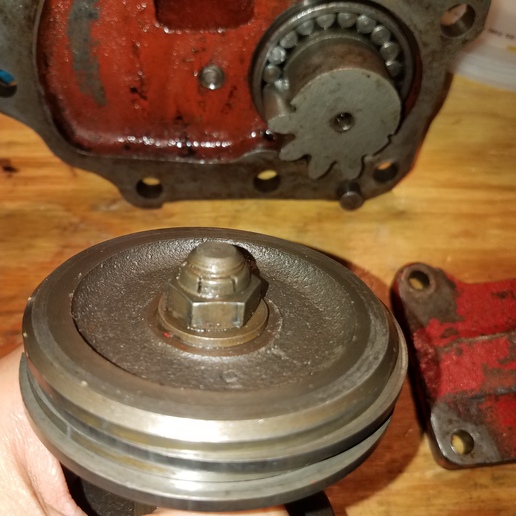
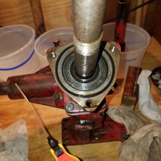
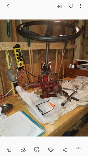
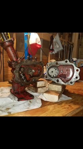
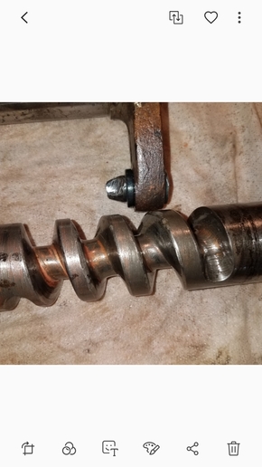
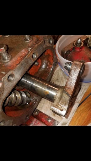
If you've not seen my previous post on this, I purchased this tractor and PS only works turning right.(I recall right). I removed and tore down. I replaced rusted damaged bearings all orings and the gear shaft pivot pin that runs up and down the spiral cam tube. I didn't replace the large oring in the hydraulic cylinder. The race,both shafts and main bearings and valve spool looked good. Some pitting on the upper steering shaft. There are dings in the spiral cam tube. See pics.
I reattached the cleaned, rebuilt assembly to the tractor. The loader and rear remotes worked great. Steering still one way. After about 2 mins. hydraulic fluid began leaking above and below the valve spool.
After removing and rechecking the entire unit I've further touched up some of the pitted and dinged areas and replaced the oring in the hydraulic cylinder. I have a couple of questions and concerns prior to reassembling.
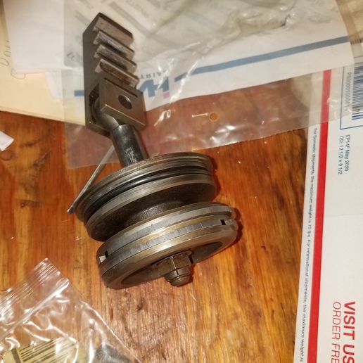
1. I was surprised at the amount of wear on the pivot pin. (See pic) The tractor only ran for a few minutes. When rebuilding I did turn the wheel dozens of times to make certain everything was working and turned it in the difficult direction a couple of times to see if it would loosen up when it was running briefly. The spiral cam tube showed no new wear. I have now smoothed out any rough edges on the tube.
Did I over tighten the adjustment screws? Does this sound like a clue as to why the PS only works one way?
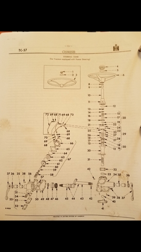
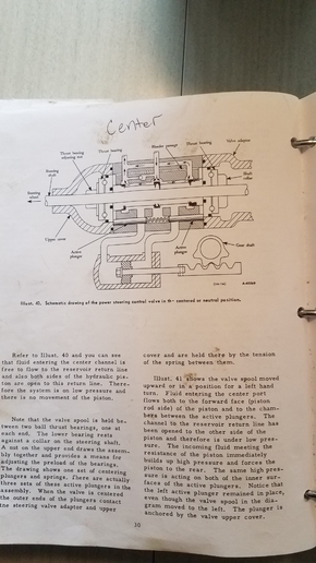
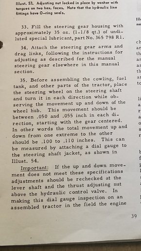
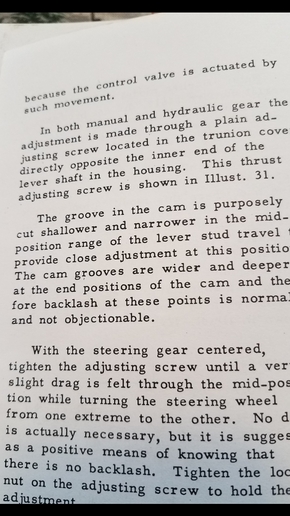
2. According to the Reassembly instructions, the steering shaft ad measured at the steering hub is supposed to rise and fall a total of .1 to .15 inches when the steering is turned completely left to right. Mine does not seem to be rising or dropping at all. I understand in part why it's necessary and understand if there is a blockage in the passages of the valve spool it will prevent the steering from working correctly. My question is what literally causes the up and down movement? Is there a groove somewhere the shaft rides on. Am I over tightening the adjusting nut? I loosened the nut when I removed the unit and couldn't measure a change. The up and down movement seems like it's a key to the correct flow of fluid in the cylinder. I included a drawing from the manual that shows the internals of the cylinder.
Let me know what you think about these items and anything else that might be causing this issue. I have read of this one way issue occurring to others but have not read of a conclusion.
Thanks! Paul

I reattached the cleaned, rebuilt assembly to the tractor. The loader and rear remotes worked great. Steering still one way. After about 2 mins. hydraulic fluid began leaking above and below the valve spool.
After removing and rechecking the entire unit I've further touched up some of the pitted and dinged areas and replaced the oring in the hydraulic cylinder. I have a couple of questions and concerns prior to reassembling.
1. I was surprised at the amount of wear on the pivot pin. (See pic) The tractor only ran for a few minutes. When rebuilding I did turn the wheel dozens of times to make certain everything was working and turned it in the difficult direction a couple of times to see if it would loosen up when it was running briefly. The spiral cam tube showed no new wear. I have now smoothed out any rough edges on the tube.
Did I over tighten the adjustment screws? Does this sound like a clue as to why the PS only works one way?
2. According to the Reassembly instructions, the steering shaft ad measured at the steering hub is supposed to rise and fall a total of .1 to .15 inches when the steering is turned completely left to right. Mine does not seem to be rising or dropping at all. I understand in part why it's necessary and understand if there is a blockage in the passages of the valve spool it will prevent the steering from working correctly. My question is what literally causes the up and down movement? Is there a groove somewhere the shaft rides on. Am I over tightening the adjusting nut? I loosened the nut when I removed the unit and couldn't measure a change. The up and down movement seems like it's a key to the correct flow of fluid in the cylinder. I included a drawing from the manual that shows the internals of the cylinder.
Let me know what you think about these items and anything else that might be causing this issue. I have read of this one way issue occurring to others but have not read of a conclusion.
Thanks! Paul