Farmall M - 6V or 12V? - take 2 - with images

Hi All,

I am guessing 6V but just not sure - no id marks legible on anything (starter, ignition coil, generator etc), wiring is a mix of 2 gauge and 4 and no light bulbs or battery to help id.

Can anyone id from these photos?


cvphoto51912.jpg


cvphoto51913.jpg


cvphoto51914.jpg
 
I'm going to say 6volt. Can you tell on the coil which wire is marked + or- if the + goes to the distributor its 6volt positive ground, if the - goes to the distributor its 12v negative ground
 
your distributor is a delco remy unit, not an ih. it was a common unit to replace a magneto in days gone by. there are a couple set screws, iirc, one on the distributor and one on the drive housing. remove them, screw a zerk in, and give them a couple pumps of grease. then put the plugs back in.
 
definitly a 6 volt system . 12 volt never had the adjustable generator pully so dont even need to look up numbers. you did not pay attention to my reply as i said that and you still not sure. answer back with what we post. distributor is not original, probably a delco.
 
One way to sort of know it take an ohm reading across the 2 small terminals of the coil. 1.5 ohms is 6 volt coil 3-4 is a 12 volt coil if I am remembering right
 
and i said there was no 12 volt battery's then when those tractors were built. the diesels were 12 volt but used 2 6 volt batteries in series.
 
Clean the paint off the generator tag and post the delco number and that will let me tell if it started out 6 volt.
 
Hi Rustred,

Actually, I did read every post; dunno why you seem to take offense to me posting pics and asking for clarification.

Maybe upon reading your original post and not understanding what an adjustable generator pulley is, and then reading the other posts asking for pics, I followed that request with my updated pics, including the generator in question.

Thank you for providing the requested clarification that this is, in fact, a 6V system.

Best,

CnB
 
The thing on the top of the ^v Generator is either a voltage regulator, or a cutout relay. Currently it is bypassed using a grounding wire from the F terminal on the gen, to the screw holding the saddle mount.
Your light switch should have 4 positions from far CCW to full Clockwise. your starter also has no switch on it, so it will use a bog push buttom located where the operator can push it manually. If your tractor is late 40s early 50s it could be a 3 position light switch. we need to know. I have included a wiring diagram from Bob M (who is a Guru on this site). Putting it back to original is OK, or making it 12volt is OK but different, and might be cheaper. The big cables need to be 00 gauge the Bat to amp meter needs to be 10 gauge, the gen to Arm on the generator needs to be 10 gauge, the wire form the other side of the amp meter is 10 gauge , and all others can be 12 gauge. Tell us what you are doing so we can help. There are good quality complete harnesses (not including the Big Cables) sold on this site. Jim

cvphoto51923.gif
 
Hi Glennster,

If I understand correctly, you are saying this started as a magneto system and then someone changed to ignition coil, yes?

Reason I ask is I have been looking at pics of other people's Farmall M's online and many, if not all, seem to have the distributor facing the same way as when it was a magneto system - but this one has the distributor facing up.

Just wondering why that is and how, since the plugs were pulled I can identify which plug goes to which cylinder since the book has it facing a different direction.
 
and i told you what u have , so now what ? i am not taking offence, but people dont listen to advise and keep on asking questions. self explanitory ... you need to adjust the generator pulley to remove the belt or tighten the belt. you can think what you want thats the trouble here, people get ------ at correct answers and listen to hearsay. i knew all about that pully at about ten years old when dad welded his solid cause the threads were stripped. plus worked with these old tractors for over 50 years. instead of listening, posters and readers like to jump on a person for giving right to the point answers. guess when us old guys die so will the old tractors.
 
Hi Janicholson,

My goal would be to get it running for the least amount of money possible.

I have a bunch of wire and can rewire the whole thing if need be.

For the position switch, there is off, then 3 clicks - so is that a 4 position or 3 position switch?

I found two different wiring diagrams online from, I believe, Bob. One, as shown in your post, and a second which shows what seems to be the a similar image with a 6v voltage regulator with 4 pins, 3 on one side and 1 on the other.

This thing atop the generator has only 3 pins, two on one side and one om the other, which is throwing me for a loop.
 
Your ight switch is 4 position. Full CCW is Low charge-- next in High charge-- next is high charge and dim lights-- next is high charge, and bright lights. LHDB are supplsed to be decals near the pointer on the switch. This also leads me to believe it was originally a cutout relay design. There is one easy way to find out if the thing on the gen is a regulator (it is not wired correctly, and it might have been replaced by others, so open it up and look. Take the lid off. If it has two electrical tower like gizmoes inside, it is a regulator. this might just create more headache, but here is how a regulator works: Conventional VR internal workings consist of at least two, if not three components that do the controlling.
The first is a cutout relay (it is also in a cutout (duh)). It is a normally open magnetically closed switch. It has two windings around the metal core of the unit. A pull in winding, and a hold in winding. This Cutout relay disconnects the generator from the battery by opening a heavy set of contacts. It is always open when the generator is not spinning. It will close when the newly spinning generator makes enough voltage on its own from residual magnetism in the field pole steel, to generate enough voltage to pull in the contacts. (Pull in winding).
The hold in winding is heavy wire made to handle full gen output and more. It is of few turns, and holds the contacts closed firmly when the gen is putting out charging voltage. The cutout will disconnect the generator if the generator output (at idle for instance) drops below the charging voltage of the battery (less than bat volts).
It does this so that battery current is not sent into the gen armature and then to ground. The battery would discharge rapidly in this case through the gen windings because it would be higher voltage than the gen. Electrons running the wrong way. The Cutout is also set to open when the tractor is shut off (again so the generator is disconnected and not sucking battery voltage to ground. This is super important, because the battery will drain in just an hour or so, and the generator will overheat and smoke will come out of the openings. Because it is not rotating and being cooled by the rotation and position in the airstream of the tractor fan.
If you idle it down the amp gauge will show less and less charge. until it is discharging. at about 3 to 4 amps discharge, the Cutout relay will open and the discharge will be limited to the ignition draw, (adding any lights if they are on). The cutout is not connected to anything but the Gen terminal, and the Bat terminal, except that the pull in winding is grounded to the VR frame so it has a place to sent pull in voltage.
The Voltage regulating relay system is either one or two additional coils and contact systems. It is a voltage chopper. It is a vibrating set of contacts that have charging voltage (from the Armature terminal) running through its fine wire coil. This voltage goes to ground at the far side of the coil, to the VR frame. The voltage tries to open a set of contacts. These contacts are in the field circuit. There may be double contacts in this relay with two or more resistors connected to ground (usually under the floor of the VR). These resistors go to the contacts, and adjust how much the field windings in the gen are grounded. The more they are grounded, the higher the output voltage of the gen, and the more charge goes to the bat. This set of contacts is held closed by a spring that adjusts the exact amount of voltage allowed to go to the battery.
As the voltage rises, the relay contacts stay poen longer (they vibrate remember) and this chopping of the ground circuit regulates the output voltage. It is very crude and electrically noisy making and breaking current that makes magnetism. it actually makes high quality static, and radio interference. It is also why many digital meters cannot be used with an older vehicle while it is running. It is such a noisy environment, that the meter reads AC voltages instead of DC, jumping all over and giving false readings.
There may be that third coil in some regulators. It is a current limiting relay (also in series with the voltage control just mentioned. It is set to have all of the Gen out put pass through its thick wire coil. (it winds around both the Cutout relay, and the Current limiting relay on its way to the Bat terminal) Its contacts also are normally closed until the gen begins charging beyond its rated amps. (generators are not self limiting in current, and will smoke if charging into a load that is too heavy, alternators are self limiting) The heavy current opens the contacts again chopping the field ground path so that the gen output is regulated as to Amps.
I have simplified this believe it or not.
I hope it helps Jim
 
Hi Rustred,

Thank you for confirming it is a 6V system - now I get go to work on trying to get it started.

On an aside, for your edification and to reply to your post - had I been put on a tractor when I was in diapers, I too would likely be able to rebuild a tractor in my sleep, but if that was the case, I wouldn't be posting questions on the differences between a 6v and 12v Farmall - now would I? No, I would have just fixed the tractor.

Similarly, dunno who you have dealt with on here that have gotten upset by being provided correct info to a question - but as that is not me nor what I did, I cannot say.

Also, if it was self-expanatory, then I would not have needed additonal clarification - hence the defintion of self-explanatory.

Lastly, I do appreciate being advised on the right info and what/how to determine said info, but put yourself in my position.

If we go by even your own original post, you implied a request for pictures from which to assist (which I provided - then seemed to take offense that I did such a thing); asked if I knew the difference between a 6v and 12v battery then when on to say it wouldn't matter and indicated an adjustable generator equates to a 6v system (which I have already admitted to not knowing what such a thing is, i.e. not self-explanatory).

Couple this with 15 other people posting their input and to me, your reponse is but just 1 of many, so to assist in solving the question, I posted the photos - which, by the way, answered the question.

So think what you will about what people do with their posts, but I for one, am happy with the methodology and outcome.

Again, I do really appreciate the info and thank you for notifying me that it is in fact a 6v system.

Just a thought, maybe YT can institute a badge or notifier under a person's handle which signifies this person is erudite on a given subject, thereby advising the reader/poster which response is most likely to be accurate/of benefit - just think, with a such a system you would be "King Rustred, all knowing oracle on Farmall" 😀.

All jokes aside, even if I could click on a reply and mark it as having been the correct or most helpful, it certainly would make searching/reading old posts much more beneficial.
 
Gotcha,

So this should be a cutout relay but instead someone put on a later style voltage regular?

If that is the case, shouldn't the voltage regulator being doing the work of the light switch resistor (ie the light switch resistor should not be connected)?

If yes, then would the correct wiring be to have the battery connected to the ammeter by the seat, then the ammeter connected to the voltage regulator at the battery connection.

Then the field terminal on the generator connected to the f terminal on the voltage regulator?

Lastly, the armature terminal on the generator connected to the generator terminal on the regulator?

In theory the light switch resistor is being bypassed and the vr controls the resistance to ground?

But, mine is currently wired with the voltage regulator f terminal grounded to the case and the light switch resistor wired to the field termimal on the generator.

Why would this be?

My first thought is the voltage regulator has an issue and whomever tinkered with it bypassed the resistor in the regulator and instead hooked it up the the light switch resistor?

Or, is it possible that maybe this VR is fixed output and to bypass for variable output from the generator it is hooked up to the light switch relay?

I can run a continuity test on the generator and relay but not sure how to do that with it hooked up to the tractor - thoughts?
 
(quoted from post at 20:32:28 07/30/20) Hi Rustred,

Thank you for confirming it is a 6V system - now I get go to work on trying to get it started.

l.
theres no way to tell that generator is 6 volts by a picture
Like D Slater said the tag number will only tell you what it started out as. It could nave been converted to 12 volts by simply changing the fields and regulator many years ago. Delco also built generators that took the adjustable pulley so thats not an indicator.
the wire grounding the fields indicates someone did not want to use the light switch to control the charging or the regulator did not work depending on what you got there. ground the fields on Delcos and you get full output
it puzzles my why you want to know. did you just get the tractor and it has no battery. if thats the case check the size of the battery cable ends. the positive terminal is larger. if the cable with the larger ID is the ground cable its surely a 6 volt pos ground
 
THe light switch is two switches on one shaft. One switch has control of the lights, one switch has control of the generator output.
The switches are rotated together and both have resistors in their circuit. The light switch is supplied from the amp meter through a 15 amp fuse, and is on Dim (through the wire wound resistor) in the third switch position, and Bright in the far CW position (direct 6 volt to lamps).
The first two switch positions are "off".
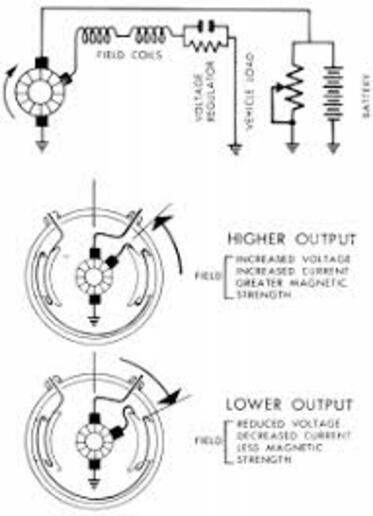
The Charge control is a grounding task, and the switch grounds the generator field either through a resistor, Low charge, or,directly to ground, High charge. the electrical path is a bit complex, bear with be. The generator has three brushes inside. One is connected to the Arm terminal of the VR. one is grounded, and one is adjustable, but near the brush connected to the Arm, not the grounded one. Electricity is sourced by this third brush, and sent to the gen field coils on the outside of the gen body. From there, the voltage needs to find ground o be complete/flow. The light switch provided that grounding. A single wire in the loom went from the F terminal, to the light switch for grounding. At the switch the field was always grounded (either some through a resistor, or fully directly through the switch body to the electrical box, through the steering support column, then the tractor frame parts to the grounded positive terminal(where the electrons ended up back in the battery soup.(remember electrons flow from negative to positive.
The gen output, when the tractor is shut off, is created by left over magnetism in the field pole iron. This electricity is strong enough to reach battery voltage when not connected to a big load, but strong enough to latch the cutout, connecting the battery to the generator. Now the fields have full power connection, and the charging voltage/current travels through the cutout, to the amp gauge, from there to the battery negative terminal. The field ( when a tractor is ordered with no lights) travels to the Cutout relay, where a simple resistor is used (separate from the cutout) to ground the F terminal through a resistor. This limits a "no lights" tractor to low charge all the time.
If a regulator is used, There is no use for the light switch grounding circuit, so the switch for the gen control is disconnected, or not there if OEM with a regulator. Regulator F terminals are the only thing connected to the F terminal of the gen. The vibrating points in the regulator (voltage control relay part) chop the electricity into bits, creating an average ground for the field, that controls output voltage of the gen. Nothing is as simple as it seems. Your generator field should not be under that screw. It may be wired so wrong that things will smoke or start fires if started. Jim

cvphoto51930.jpg

Info
 
Gotcha,
I agree the field generator should be going to the voltage regulator or the light switch resistor.

But I am curious if grounding the field generator to the case creates the same circuit as in a generator with no light switch or regulator (ie and internally grounded generator - where the field wire is grounded to the case inside the generator).

Interestingly, on this tractor, the field is grounded to the case and the field post on the the vr is connwected back up to the switch, which seems pointless, no?
 
Wait, I was reading that incorrectly...

I am correct in saying we both agree the field terminal on the generator should be connected to the vr "f" terminal OR the the field terminal on the generator should be connected to the resistor in the box with the light switch, yes?

But, where I was incorrect below and originally read incorrectly is we don't want to directly ground the generator because under grounded field condition the generator runs at either high or some preset output, and when resistance to that ground is applied the generator slows or stops, yes? Meaning a grounded field generator, as you said, could burn up, or, I guess ideally, trip the fuse?

So in theory, wouldn't I be safe be not doing anything with the generator F terminal and simply disconnecting that wire?

Also, couldn't I simply disconnect the armature wire from the battery to the voltage regulator as well?
 
I am telling you in no uncertain terms, do not put a battery in this machine till it is rewired, or it may go up in smoke. There are two generator types. A circuit (like this Delco) and B circuit (autolite/ford/others). The A circuit field (the magnets) are supplied with power internally and grounded externally to make magnetism. The B circuit, type (not yours) has the windings grounded inside the generator, and electricity supplied by the VR to make the magnetism. Not compatible, not in consideration here. Jim
 
Much better thinking. But generators with 3 brushes like yours are set to put out a charging voltage that is OK for a charged battery ~ 7 volts. This will not burn things, and there are no fuses in the generator circuit! What I am telling you is that with the deteriorated wiring, and clearly incorrect wiring, I cannot recommend putting a battery in it. Jim
 
Hi Jim,

Oh, I get that.

I can re-do the wiring today without issue.

Just wondering, without testing the charging system, and considering I am focused on the engine/starting/running, couldn't I disconnect the generator completely to avoid any potential damage.

I guess the big question would be if I make 2/0 wires for the battery/connections under assumption it will be a 6v system when done, then later find out it would have been cheaper to convert to 12v system but wasted my 2/0 wiring...

Maybe I should pull the generator and test, but am thinking I need to remove things to test, no?
 
Ding ding ding! 😀

I measured the resistance of the coil on this tractor, 1.4 ohms - then measured the ohms on my Farmall 400 6v, 1.4 ohms.

We have a winner - 6v system

Thank you for the input 😀
 
your picture shows the original cut-out on the top of a 6v generator and they grounded the field to make it charge you should have the battery hooked positive ground. If the system is charging grounding the field means the cut-out is bad or the points are dirty. Just worked on one and cleaning the points of the cut-out made it work again many are running around with the field grounded and have been that way for many yrs just adjust the third brush for out put and go
 

We sell tractor parts! We have the parts you need to repair your tractor - the right parts. Our low prices and years of research make us your best choice when you need parts. Shop Online Today.

Back
Top