
On a 1949 Case VAO, I've got spark, it's cranking well, but there is fuel being spit out the exhaust and it won't fire. When I pull the plugs after that, they were soaked in gas, so it's flooding the engine while it cranks. Does anyone know what is causing this? The tractor is sitting in a field, has been for at least two years, with a bucket loader on it, so I HAVE to get it running to move it. Any speculation/knowledge on what to look at would be appreciated, as I need this moved in the next month.
You are using an out of date browser. It may not display this or other websites correctly.
You should upgrade or use an alternative browser.
You should upgrade or use an alternative browser.
- Thread starter CaseyCub
- Start date
Bad float or stuck float or dirt/rust in the float needle seat. One that has sat that long in a field the float could very easily be stuck of it could have gotten some water in the carb and had it freeze and that will destroy a float. But one can in fact tow a tractor with a loader by snaking a chain under the bucket and then hooking it up to some frame work up say 1-3 foot up so when you pull the bucket comes up and then stays that way as long as your pulling
Klyde
Member
- Location
- Upstate NY
Ice in the air cleaner? No spark. OLD gas.
Got the carb off and apart on the workshop bench, cleaned out (LOTS of gunk in the bottom and in the various ports came pouring out of it). Only problem is I made a rookie mistake: I pulled the jets out before I screwed them in to see how they were set. Any idea what the settings are supposed to be on it, or where I could find them? On the side of the carb float bowl is "MARVEL" and below that is "SCHEBLER", both molded onto the metal; and directly opposite the throttle linkage is "48" "TSX" and "114" stamped into what appears to be an irregular-shaped brass plate.
TSX carb adjustment at the bottom of manual page 12.
Joe
http://www.carburetor blog.com/manuals/dltx_tsc_manual.pdf
Joe
http://www.carburetor blog.com/manuals/dltx_tsc_manual.pdf
Got the carb set, got it on, now I don't have spark again! Last time it was the distributer cap/rotor was corroded. Been swapping parts with the other, running VAO in this farmyard, and so far the coil, cap, rotor, plugs, wires, and connections are all good. I THINK it's the on/off switch on the dash, someone replaced the pull/push with a toggle, and I don't think the toggle was weather resistant enough! I'll test that tomorrow, ran out of light for the day. Thank you everyone for the carb help!
This thing doesn't have points. It's got a cap and rotor, but no points. When I took the on/off switch off, it revealed a broken wire, which I'm going back up the road to replace as soon as the downpour lets up a bit. Switch tested fine with a light circuit tester I made myself.
I've used that bypass wire you mentioned on my Cub Cadets, though! It really is handy.
I've used that bypass wire you mentioned on my Cub Cadets, though! It really is handy.
J Hamilton
Well-known Member
- Location
- Southern Illinois
Like old said, it has to have one or the other. Can you take a picture to post here of the distributor with the cap, rotor and dust cover removed so we can see what's under there to help you better?
I unfortunately do not have the technology available to me to take a picture and put it on the internet. Perhaps I'm missing something in this discussion. May I recount what's been done so far? Under the distributer cap is the rotor and the 4 contacts that the rotor hits. The contacts and rotor are not burnt or dirty, the plugs are clean, the wires and connections are clean and secure. The kill switch is good, the battery is good, the cables are clean and in good condition, and I fixed all the broken wires. Maybe I'm just used to the Kohler engd, you mentioneines in the Cub Cadets, but I could not identify a points cover on this Case tractor engine. J Hamilton, you mentioned a dust cover, what is that? Old, if you could point (sorry) out the points location on a VAO, I could give the bypass wire a try.
TractorTucker
Member
The dust cover is under the rotor, under the dust cover is the points and condenser.
Plugs are still dry, even after repeated cranking and manipulating the throttle. PLENTY of fat sparks on the points, and plugs when tested out of the engine. I confess, this is starting to frustrate me. I've done everything that everyone has suggested now, and the durn thing still refuses to fire. Plugs, points, cap and rotor, carb, and a few new wires and cleaned every connection. All it's done so far is wear down 3 batteries.
J Hamilton
Well-known Member
- Location
- Southern Illinois
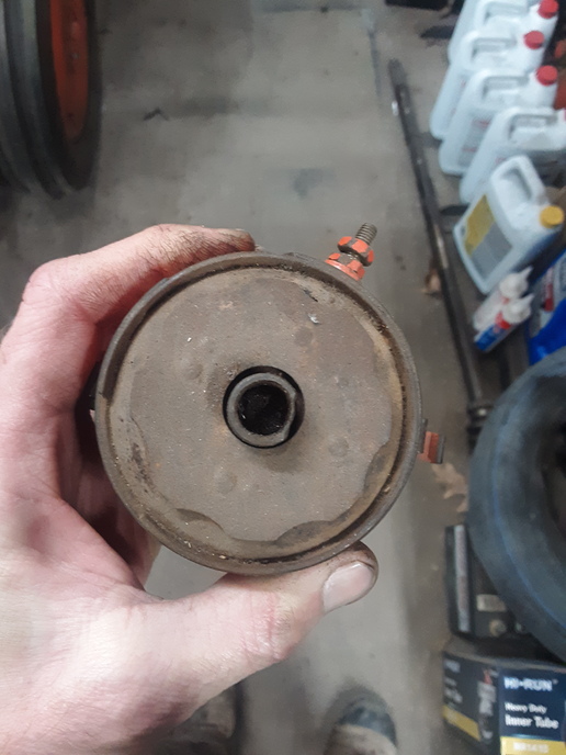
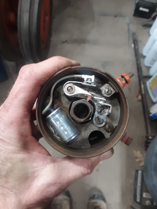
The first pic is the dust cover with the cap and rotor removed. Second pic is the points and condenser under the dust cap. Hope this helps.
I know this may not be easy to do but pull the rubber tube between the carb intake and air cleaner then hold you hand over the air intake of the carb and try to start it. You should both feel a good suction and also get gas on your hand. It may even try to start when you do that
J Hamilton
Well-known Member
- Location
- Southern Illinois
Have you verified the plug wires are in the correct position on the cap for each plug for the correct firing order?
J Hamilton
Well-known Member
- Location
- Southern Illinois
The correct firing order is 1-3-4-2
J Hamilton
Well-known Member
- Location
- Southern Illinois
Have you tried spraying a little carburetor cleaner in the intake while cranking to see if tries to fire at all?
This is the distributor factory attitude for VA series and how to install and time. Firing order is 1342, timing set TDC, points gap 0.020", plug gap 0.025" Distributor need not be set at factory attitude to run an engine but must fire in correct firing order at or near TDC on the compression stroke.
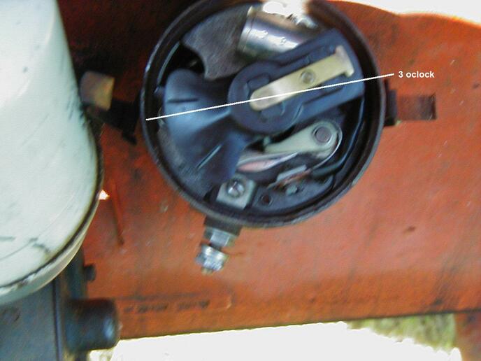
Rotate the crankshaft (CW as viewed from the front) until #1 cyl is TDC on the compression stroke (make sure it is not TC on the exhaust stroke). The factory distributor attitude is with the rotor pointing near 3 o'clock to fire #1. When the engine is running the rotor will be turning CW.
Looking down on the distributor:
Stab the distributor with the rotor in place. The dist drive gears are helical, as the gears mesh the rotor will turn CCW so start the stab with the rotor pointing somewhere after 4 o'clock and when in full mesh the rotor will end up pointing near 3 o'clock when the distributor is seated.
When you get the rotor in that position tighten the hold down bolt. Loosen the clamp screw and turn the dist head until the breaker actuator is on the top of the cam lobe, set the points @ .020" with a feeler gage. Turn the dist head CW until the points are closed now turn the head back CCW until the points just start to open and tighten the clamp screw.
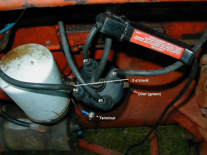
The engine firing order is 1342 and the rotation of the rotor is CW so when you put the cap on, put the #1 cyl wire in the tower that is near 3 o'clock, #3 wire near 6, #4 wire near 9, and #2 near 12. That is good enough to start the engine and tweak the timing in to TDC with a timing light.
The TDC timing mark may be just a line ascribed on the flywheel sometimes marked with “0” or other marking that changed over the production years. The IAD 6003 distributor starts to advance at 570 rpm so you need to set the initial timing preferably between 400 - 500 rpm. If you are using an induction timing light and cannot find the timing mark running at idle rpm and turning the distributor head, put the timing light pick-up on the coil wire. That will provide 4 times the light flashes to light up the timing hole. You can time the engine with the induction pick-up on either #1 or #4 or the coil wire, it is all the same timing.
Joe
Pic 1 is factory attitude static timing showing rotor in position to turn CW about to fire #1 cylinder.
Pic 2 is factory attitude firing order. Clamp is induction timing light pickup on the coil wire.
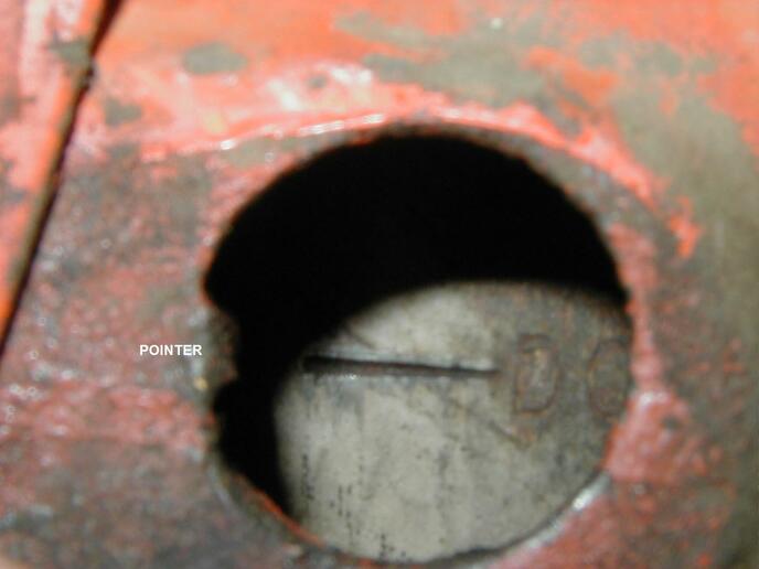
Pic 3 is flywheel timing hole on the left side bell housing. It may have a cover with a bolt hinge to swing it open. Line up the TDC line on the flywheel with notch on the bell housing.
Rotate the crankshaft (CW as viewed from the front) until #1 cyl is TDC on the compression stroke (make sure it is not TC on the exhaust stroke). The factory distributor attitude is with the rotor pointing near 3 o'clock to fire #1. When the engine is running the rotor will be turning CW.
Looking down on the distributor:
Stab the distributor with the rotor in place. The dist drive gears are helical, as the gears mesh the rotor will turn CCW so start the stab with the rotor pointing somewhere after 4 o'clock and when in full mesh the rotor will end up pointing near 3 o'clock when the distributor is seated.
When you get the rotor in that position tighten the hold down bolt. Loosen the clamp screw and turn the dist head until the breaker actuator is on the top of the cam lobe, set the points @ .020" with a feeler gage. Turn the dist head CW until the points are closed now turn the head back CCW until the points just start to open and tighten the clamp screw.
The engine firing order is 1342 and the rotation of the rotor is CW so when you put the cap on, put the #1 cyl wire in the tower that is near 3 o'clock, #3 wire near 6, #4 wire near 9, and #2 near 12. That is good enough to start the engine and tweak the timing in to TDC with a timing light.
The TDC timing mark may be just a line ascribed on the flywheel sometimes marked with “0” or other marking that changed over the production years. The IAD 6003 distributor starts to advance at 570 rpm so you need to set the initial timing preferably between 400 - 500 rpm. If you are using an induction timing light and cannot find the timing mark running at idle rpm and turning the distributor head, put the timing light pick-up on the coil wire. That will provide 4 times the light flashes to light up the timing hole. You can time the engine with the induction pick-up on either #1 or #4 or the coil wire, it is all the same timing.
Joe
Pic 1 is factory attitude static timing showing rotor in position to turn CW about to fire #1 cylinder.
Pic 2 is factory attitude firing order. Clamp is induction timing light pickup on the coil wire.
Pic 3 is flywheel timing hole on the left side bell housing. It may have a cover with a bolt hinge to swing it open. Line up the TDC line on the flywheel with notch on the bell housing.
No, I haven't. I asked this question on another tractor group as well, and someone else suggested starting fluid. I've never heard of using carb cleaner to help it fire. I didn't try any kind of starting aid because I didn't think it would make it through the oilbath cleaner. Never crossed my mind to remove the rubber tube between the breather and the air intake until someone mentioned it. That is now first on the list in the morning. I'm running out of free time daylight hours!
J Hamilton
Well-known Member
- Location
- Southern Illinois
Hopefully everyone's suggestions will help you get it going! At least enough to get it moved
Timing checked out, gave the carb a second cleaning, then a third. An hour of scraping and poking, two cans of carb cleaner, and several dropped screws later, it fired to life! Thanks to all who helped out here, not just for the advice, but the patience with a newbie! Next time, hydraulic pump!
J Hamilton
Well-known Member
- Location
- Southern Illinois
Great! Glad you got it going! And thanks for the update.
J Hamilton
Well-known Member
- Location
- Southern Illinois
You're welcome. I don't know a lot about hydraulics, but there are others on here who know hydraulic systems pretty well.
Similar threads
- Replies
- 9
- Views
- 292
We sell tractor parts! We have the parts you need to repair your tractor - the right parts. Our low prices and years of research make us your best choice when you need parts. Shop Online Today.
Copyright © 1997-2024 Yesterday's Tractor Co.
All Rights Reserved. Reproduction of any part of this website, including design and content, without written permission is strictly prohibited. Trade Marks and Trade Names contained and used in this Website are those of others, and are used in this Website in a descriptive sense to refer to the products of others. Use of this Web site constitutes acceptance of our User Agreement and Privacy Policy TRADEMARK DISCLAIMER: Tradenames and Trademarks referred to within Yesterday's Tractor Co. products and within the Yesterday's Tractor Co. websites are the property of their respective trademark holders. None of these trademark holders are affiliated with Yesterday's Tractor Co., our products, or our website nor are we sponsored by them. John Deere and its logos are the registered trademarks of the John Deere Corporation. Agco, Agco Allis, White, Massey Ferguson and their logos are the registered trademarks of AGCO Corporation. Case, Case-IH, Farmall, International Harvester, New Holland and their logos are registered trademarks of CNH Global N.V.
Yesterday's Tractors - Antique Tractor Headquarters
Website Accessibility Policy