Case VA (VAO) 12 volt wiring diagram

Britcheflee

Well-known Member
Hello,
I am working on a Case VA or might be VAO there is no serial number - I can post some pics if needed. It has been converted to 12 volts with a motocraft alternator which was run though a VR. There seemed to be some issue with the wiring and things were smoking and melting so disconnected it all. I would like to replace that motocraft alternator with the single wire alternator and remove the old VR (I will replace the coil and resistor in due course) my problem is that all the wiring diagrams I find on line do not show for this exact model which has the switch and also the press button starter like on an 8N - I cant get it to match up with what I have on the tractor. Can anyone in simple terms explain how to wire this up and/or show me a diagram or post a picture of their set up?
mvphoto52504.jpg


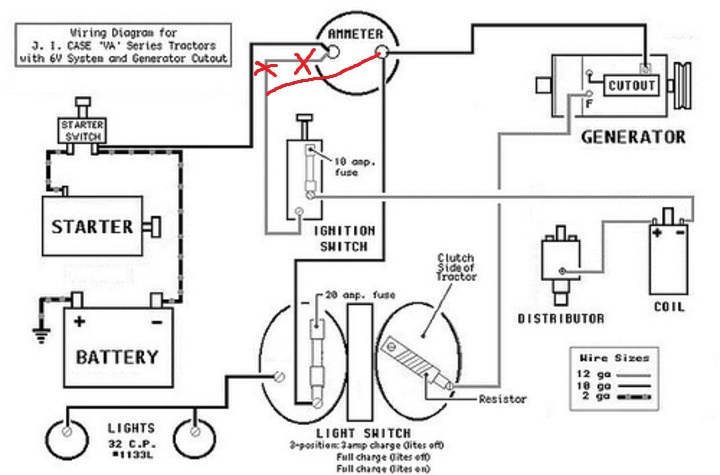
This is the existing wiring set up - I have ordered a new set of gauges as these are in really bad shape. The wire on one side of the ammeter is just disconnected as it went to the old VR before.
 
You are not going to find a wiring diagram for either what you have or what you want to set up, you're going to have to start from scratch and design it. I like your idea of new gauges, and from what I can see from your pics, I suggest all new switches and wires also. It should not be difficult but I recommend you enlist the help of an old-school mechanic, one with a decent theoretical background and a lot of experience.
 
I use a 4 postion key switch. Internal resistor coil. ACC to alternator excite. On side of key switch to pos side of coil. Use an old automotive solenoid. Pos battery to
one side of solenoid. Fuse like on post with battery cable. Fuse like to battery key switch. start side of key switch to small wire on solenoid. other big post on
solenoid to starter. use a voltmeter pos and all gauge lights to on side of keyswitch. negative side on voltmeter to ground.
 
Here is a VA diagram original 6 volt system, positive ground, with cut-out and switch controlled charge level to the field post on generator.

On the diagram the ignition switch feed should be on the generator side of the ammeter with light switch feed.

To change to internal regulated Delco 10 SI alternator common on early 80?s GM vehicle:

Remove generator and cutout. Disconnect generator field wire at generator and light switch.
Mount the Delco alternator
Cutout wire that went to ammeter connects to output on the alternator. I would recommend 10 gauge wire from alternator to ammeter and ammeter to starter switch. 14 gauge will be fine for other wiring.
That connects it as a 1 wire alternator.

On the coil, switch input goes to + and ? goes to side of distributor with negative ground.

If using a 3 wire alternator connect #2 pin on alternator down to output stud, and #1 pin to coil side of the ignition switch and add a diode (3 amp, 50 volt, marked band toward alternator) or a 194 lamp in the wire from #1 to switch. Without this isolation the tractor may continue to run when switch is turned off.

Replace 6 volt lights with 12 volt.

Install 12 volt battery with negative ground.

With light switch on, engine not running, the ammeter should show negative. If it shows positive reverse ammeter connections.

Starter turns the same direction regardless of polarity. Original starter should still work with 12V.

6 volt coil (1 1/2 ohms across primary) needs a 1 1/2 ohm resistor between coil and ignitions switch, or replace coil and resistor with ?12 volt, no external resistor required? coil (3 ohm primary) such as NAPA IC14SB or equivalent.

Replace any other worn or defective wires.


cvphoto1694.jpg
 
There is a new plug and wires to replace the original 2 wire connector on the alternator that has a diode in the circuit. It,s kind of handy. I get mine from a local parts house.
 

We sell tractor parts! We have the parts you need to repair your tractor - the right parts. Our low prices and years of research make us your best choice when you need parts. Shop Online Today.

Back
Top