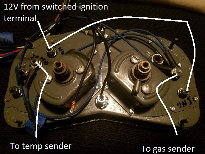
630 gas gauge cluster wiring

400ss

Member
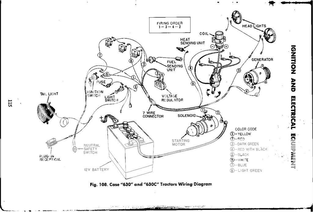
Does anyone have a diagram for the Stewart
warner gauge?
a151622.jpg
 
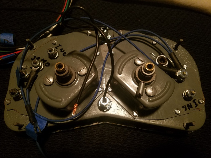
It looks like you have the sender terminals wired in series. You should have a single wire on the gas gauge sender terminal to the gas tank sender and a single wire from the temp gauge sender to the temp sender on the engine. It is ok to have the ign terminal wire on both gauges in series and connected to a switched terminal on the ignition switch for power.

Joe
 
Actually, he has the sender terminals in PARALLEL. The "IGN" terminals should be in parallel, instead.
 
I thought that I had made a post this morning on how to wire this thing. Power has been down since last night @ 2200 and my computer gets a little squirrely on the generator. I'll try to post again.

Bob is right. I was looking at the terminal on the lower left to the temp gauge sender terminal as an input when it is actually intended to be an output. Still the sender terminal on the temp gauge and gas gauge should not be wired together. I made up a lot of wiring diagrams when I was getting Roger Hornbaker started on replacing the defective mechanical temp gauges with electrical SW resistance gauge on the restored clusters that he was selling on ebay as "everything works except the temp gauge".

I restored my own cluster gauge boards. I know instrumentation repair from USN training in the early 60's but I can't even come close to Roger's cosmetic and craftsmenship. Roger is now retired so I'll post how to do it.

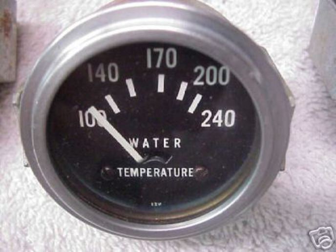
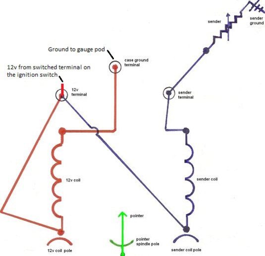
These SW gauges used by Case and many other applications of the era were common 12V 30-240 ohm resistance type that are nearly obsolete but can be purchased on ebay. The 1st pic is a typical SW resistance 30-240 gauge. Cut the bezel and take the gauge movement out of the cup. The gauge movement is identical to the SW gas and temp Case cluster gauges. It doesn't matter whether the face place is gas, temp, or oil press. The movement in the gauge is all the same 30-240 ohm resistance type. You can put your existing Case face plate on the movement and connect it to a relative 30-240 ohm sender, in this case either gas or temp. Pic2 is the electrical movement of these gauges.

Pic3 is how to wire the cluster. Check this Bob and Joe Y, I am doing this very quickly and I value your opinion.

Joe
a151671.jpg

a151672.jpg

a151673.jpg
 
Thanks a bunch guys! For the amp guage which stud is the keyed and which is the regulator? And that makes more sense now that I see it I was trying to go off of the directions with the new harness and it just wasn't making sense last night
 
Current flow in a DC ammeter is through a resistor. Polarity wise it doesn't matter which way you initially connect those wires as the ammeter will read out in the direction of current flow. If the meter reads discharge when should be showing charge or vice-versa simply swap the wires. Wrong connection will not affect the regulator or anything else in the electrical system including the ammeter which will just read backward.

Joe
 

We sell tractor parts! We have the parts you need to repair your tractor - the right parts. Our low prices and years of research make us your best choice when you need parts. Shop Online Today.

Back
Top