
Having a problem adjusting the fingers on the clutch pressure plate after replacing the clutch. I noticed that fingers were nearly out-of-sdjustment when I replaced the old slipping clutch. I followed the shop manual specs for setting the fingers, but they cannot be set to make contact with the release bearing (bearing has about 1 inch of travel). About ready to just replace the pressure plate as I do not know its history, but hate to spend the $$ if I am barking up the wrong tree. This tractor has a lot of issues from previous owner(s) cobbling it up. Any thoughts on how to attack this problem - things I may have overlooked?
You are using an out of date browser. It may not display this or other websites correctly.
You should upgrade or use an alternative browser.
You should upgrade or use an alternative browser.
- Thread starter wxford
- Start date
Jim.ME
Well-known Member
- Location
- central ME
Personally, I replace the pressure plate and throw out bearing as well when I replace a clutch disc.
I believe the D15 is the same as the D14. I don't know what you have for a manual or how it reads. My Allis Chalmers D14 manual says:
([color=darkred:fc251a2604]"Adjust all release levers evenly. There should be approximately 3/16" to 1/4" clearance between throwout bearing and release levers. [u:fc251a2604]This adjustment is made at the pedal link rod and may be checked through opening at bottom of Housing.[/u:fc251a2604]
3/16" to 1/4" clearance at throwout bearing will permit approximately 3/8" to 1/2" movement of the clutch pedal link rod, and approximately 1-1/4" to 1-3/4" movement at foot pedal." [/color:fc251a2604]
The clearance between the throwout bearing and the release levers is adjusted with the clutch pedal link rod, not the pressure plate fingers. To me adjust release levers evenly means small adjustments, if needed, so the throwout bearing contacts them squarely and at the same time. Major adjustment of the release levers would be when the pressure plate is assembled and I don't find any specs for that dimension or method to check it.
Traditional Farmer
Well-known Member
- Location
- Virginia
As Jim said false economy not to replace all the clutch parts while you have the tractor split.
Mike(NEOhio)
Well-known Member
- Location
- Newbury, Ohio
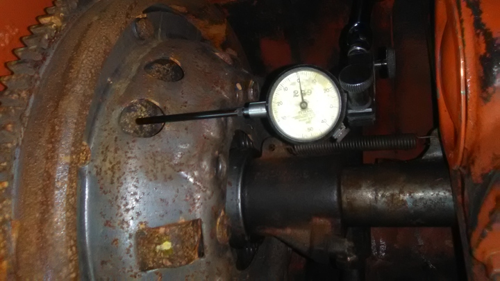
I reset the fingers on an E4 clutch by clamping it down on a table saw with spacers under it and depth-miked the fingers and checked with an indicator. I called a clutch and driveline shop and they gave me the specs. Still had trouble with the release once it was back in the tractor. I spent a few hours resetting them with a dial indicator till they worked right. Had to set one at a time and work my way around a few times.
#1. The clutch pedal rod positions the clutch pedal height. It doesn't control the maximum forward stroke of the throwout bearing. There is a stop inside the bellhousing that the clutch release fork comes up against. #2. The flywheel should have been machined perfectly FLAT and this includes where the pressure plate O.D. is located. #3. You should be able to easily adjust the finger to throwout bearing clearance once the tractor is rolled back together. If the fingers are too far away from the throwout brg (and the flywheel is flat) your clutch disc pads (4 pads) must be too thick, which will pull the fingers away from the throwout brg.
Thanks for all the replies! And I totally agree that not replacing everything is a false economy (time and money I have already wasted).
My shop manuals are the I&T AC-201, and another one just for the D-15 (I have them for the D-14, D-15, and D-17).
The clutch I replaced was the HD 70215387 and I ordered that same number. However, I got a standard clutch 70232239 and I called them on it. Apparently, the 70232239 is an after-market replacement (fit-all) for 70253187, 7024774, and 70231976, etc.? I question how that is possible when one is HD and one is Std, and there can be hub differences. So, I took measurements of the old clutch and compared to the new one, and they all seem to match up (thickness, # of splines, hub height, spline diamenter, etc.). And, the new clutch fits up to the tractor as it should. The new clutch it not noticeably thicker than the old one. I suspicion the uneven wear and slippage on the old clutch may have been due to the inability to properly adjust the fingers.
The pressure plate is machined FLAT, and I thought it would offset any thickeness issue a new clutch might cause to the finger adjustment (it didn't). However, I have no information on how thick a new pressure plate is, and how much machining it can tolerate.
I think the best plan at this point is to bite the bullet and replace the whole assembly. Any words of wisdom or things to look out for when replacing all these parts?
Thanks again!
Is the flywheel surface flat?? including the ring gear ?? Anyway, if for some reason your pressure plate has been machined to make it flat, that would move your fingers closer to the throwout bearing. So, now what do you say ??(quoted from post at 15:25:31 08/23/19) Thanks for all the replies! And I totally agree that not replacing everything is a false economy (time and money I have already wasted).
My shop manuals are the I&T AC-201, and another one just for the D-15 (I have them for the D-14, D-15, and D-17).
The clutch I replaced was the HD 70215387 and I ordered that same number. However, I got a standard clutch 70232239 and I called them on it. Apparently, the 70232239 is an after-market replacement (fit-all) for 70253187, 7024774, and 70231976, etc.? I question how that is possible when one is HD and one is Std, and there can be hub differences. So, I took measurements of the old clutch and compared to the new one, and they all seem to match up (thickness, # of splines, hub height, spline diamenter, etc.). And, the new clutch fits up to the tractor as it should. The new clutch it not noticeably thicker than the old one. I suspicion the uneven wear and slippage on the old clutch may have been due to the inability to properly adjust the fingers.
The pressure plate is machined FLAT, and I thought it would offset any thickeness issue a new clutch might cause to the finger adjustment (it didn't). However, I have no information on how thick a new pressure plate is, and how much machining it can tolerate.
I think the best plan at this point is to bite the bullet and replace the whole assembly. Any words of wisdom or things to look out for when replacing all these parts?
Thanks again!
DrAllis,
I don't want to sound overly confident as I have done stupid things like that in the past. But I am fairly sure that the clutch is installed correctly - installed just like the old HD clutch. As I remember, the clutch hub is just long enough for the clutch plate to bottom out before the pads touch the flywheel when in backwards.
But that is my worry - I'll spend the money to buy all new clutch parts, and THEN discover the problem is something else that I missed (I just don't know what that could be). I still think there is some issue with this old pressure plate that I don't see until I compare it to a new one.
Jim.ME
Well-known Member
- Location
- central ME
With all due respect to DrAllis.
I believe there is a difference in adjustment procedure between the D14/D15 engine clutches and the D17/D19 engine clutches, which may cause some confusion. My Allis Chalmers D19 manual agrees with what DrAllis says as far as adjusting the rod only controls the pedal position, not free play. The D19 manual gives dimensions from the back plate for adjusting the release levers when setting it up. The wording in the Allis Chalmers D14 manual is as I posted levers equal distance to the throwout bearing and adjust the rod to the specified clearance. I did some looking around and found an I&T manual stated not to adjust the fingers to obtain throwout bearing clearance on the D14/D15 clutch. They should be adjusted evenly when overhauling the clutch assembly. In the D17 section it says the clutch pedal adjustment does not affect free play, only pedal position. I would compare the D14/D15 clutch to an automotive clutch where I have normally had to adjust the linkage, not fingers, after replacing a worn-out clutch disc.
I believe the fingers on a D14/D15 clutch pressure plate should have been set when the pressure plate was assembled and outside of maybe a minor adjustment if they don t contact the throwout bearing evenly; they are not used to adjust throwout bearing clearance; the rod is used to set that.
I would agree with that up to one point.....The maximum forward travel of the throw out bearing is FIXED because there is a stop inside the bellhousing. All the adjustment in the world of the link rod cannot change that. The complaint is the gap between the fingers and the throw out bearing is way too great and the link rod adjustment isn't going to fix that. The fingers must be moved closer to the throw out bearing.(quoted from post at 04:30:26 08/25/19) With all due respect to DrAllis.
I believe there is a difference in adjustment procedure between the D14/D15 engine clutches and the D17/D19 engine clutches, which may cause some confusion. My Allis Chalmers D19 manual agrees with what DrAllis says as far as adjusting the rod only controls the pedal position, not free play. The D19 manual gives dimensions from the back plate for adjusting the release levers when setting it up. The wording in the Allis Chalmers D14 manual is as I posted levers equal distance to the throwout bearing and adjust the rod to the specified clearance. I did some looking around and found an I&T manual stated not to adjust the fingers to obtain throwout bearing clearance on the D14/D15 clutch. They should be adjusted evenly when overhauling the clutch assembly. In the D17 section it says the clutch pedal adjustment does not affect free play, only pedal position. I would compare the D14/D15 clutch to an automotive clutch where I have normally had to adjust the linkage, not fingers, after replacing a worn-out clutch disc.
I believe the fingers on a D14/D15 clutch pressure plate should have been set when the pressure plate was assembled and outside of maybe a minor adjustment if they don t contact the throwout bearing evenly; they are not used to adjust throwout bearing clearance; the rod is used to set that.
Jim, DrAllis is correct in his assessment of my problem. I cannot explain why the old clutch-pressure plate combo kinda sorta worked, and the new clutch in the old pressure plate is not even close. The thickness of the old and new clutches are about the same ~0.024 inch. The flywheel doesn't appear to be turned down, and the pressure plate has been machined flat which should have compensated for any increased thickness in the new clutch.
The parts book show two pressure plate assemblies: original and service. I do not know which is in this D15, or how they differ. I believe the adjustment bolts are the originals (I thought about putting longer ones in as a test).
We will see what a new clutch kit does for this problem. I hope this does not turn out like a skid steer problem that took hours and dollars turned out to be a poorly substituted machine bolt (another story for another day).
Jim.ME
Well-known Member
- Location
- central ME
Thanks to both of you for the explanations. I am looking forward to hearing what you find for the issue.
Well, here is the update at the moment.
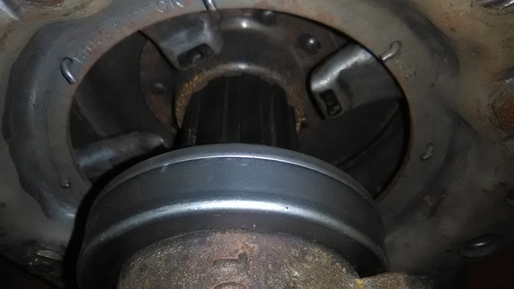
New pressure plate arrived. When I set it up to the flywheel, I got a surprise - WTF!? The ring gear kept the pressure plate from coming in contact with the flywheel!? The ring gear stands above the flywheel by quite a bit - at least the thickness of the pressure plate housing. Upon inspection of the old pressure plate, I observed that the edge had been ground down to fit. I thought that the ring gear hadn't been properly seated, and ordered a new ring gear because some of the teeth were damaged (hasn't arrived). However, when I removed the old ring gear, I discovered that it was indeed seated. It appears that the inside diameter of the ring gear is greater than the outside diameter of the pressure plate cover. This implies that the surface of the flywheel and the edge of the ring gear should be at the same height (it's not even close), and the pressure plate will overlap the ring gear and kinda hold it in place.
I don't understand this, and I question whether the flywheel could have been turned down this much. Does anyone have a good picture of what this flywheel and ring gear combo should look like on a D15 gas tractor - can't find one on the Internet and my shop manual is lacking in this regard? Thanks for the help.
I think I will change my name to baffled shade tree mechanic - LOL!
A follow-up:
I found some photos of the flywheel and ring gear, and the ring gear does stand above the flywheel surface (about half of the ring gear thickness is above the flywheel surface).
So, I am puzzled why the old pressure plate cover diameter was ground down, and the new pressure plate cover has too large a diameter. It is the correct part number and looks exactly like the old one. It looks like the old pressure plate was ground down about 1/8 inch.
I am confused...
Jim.ME
Well-known Member
- Location
- central ME
Some of the D15s used the same flywheel (70233196) and ring gear (70233197) as the D14s. I checked a used D14 flywheel I have and the ring gear on it is about 1/8" above the flywheel clutch surface. I am not sure but don't think it has been resurfaced. The pressure plate fits inside the ring gear. DrAllis can likely answer about the later flywheel (70237065). A thought is it may be the same cover plate as another clutch set up uses, but they missed the need to reduce the diameter for this application. What does your supplier say about it?
Jim, thanks for the reply!
I haven't followed-up with the supplier (Y-T) with this latest revelation. I may waited until the ring gear arrives. The pictures aren't the best, but it appears that the correct ring gear may have a groove in it where the pressure plate fits up to it (not sure). I am jumping to the conclusion that it may have an incorrect ring gear installed, and the new one will solve the problem.
With your info, I am gonna see if my flywheel has a part number on it - may tell me something.
Jim.ME
Well-known Member
- Location
- central ME
I took another look at the flywheel I have and tapped the ring gear to find the interface. If yours is the same as a D14 these photos may help you determine the issue. Did someone flip the ring gear over to buy some time due to bad teeth. I've seen that done on ring gears that are the same on both sides.


Jim.ME
Well-known Member
- Location
- central ME
I agree the pressure plate must bolt flat to the same plane as the clutch disc is on; on this clutch set up. However something must be off on our descriptions here. I can find several photos of D15 flywheels on the web and they all have the face of the ring gear above the clutch surface. To machine the ring gear flush or below the clutch surface would remove the lead in bevel for the starter drive and some tooth area. There are photos of at least one D15 (SII) clutch installed on a flywheel, in a thread on the other Allis site, and the pressure plate in that photo sets into the recess inside the ring gear, as did the pressure plate on the D14 flywheel I posted photos of. Photos of new ring gears for sale on eBay show the recess. Not to say I believe everything on the internet, just saying what I'm finding and seeing.
wxford mentioned the outside of his original pressure plate had been ground smaller. Is it possible a ring gear without the proper relieved area for the pressure plate was installed on the flywheel, the pressure plate diameter was ground to make it fit inside the incorrect ring gear, as a field fix? Just my thought.
wxford mentioned the outside of his original pressure plate had been ground smaller. Is it possible a ring gear without the proper relieved area for the pressure plate was installed on the flywheel, the pressure plate diameter was ground to make it fit inside the incorrect ring gear, as a field fix? Just my thought.
I've attached some photo that show the flywheel and ring gear (it has been removed). There is a space between where the ring gear seats and the flywheel. My old ring gear is not machined to accommodate the pressure plate. I think I might have an incorrect ring gear - the new one will tell the story.
DrAllis, you are absolutely correct (and I worry) that all of this business about the flywheel and ring gear won't solve the problem with the pressure plate fingers being too far away to make contact with the throw-out bearing.


DrAllis, you are absolutely correct (and I worry) that all of this business about the flywheel and ring gear won't solve the problem with the pressure plate fingers being too far away to make contact with the throw-out bearing.
Jim.ME
Well-known Member
- Location
- central ME
Don't get me wrong, I'm not implying this will fix the problem with the finger height. Correcting this will let your pressure plate bolt up properly, without modification, as a starting point.
If you have waiting time, have you bolted the new clutch and pressure plate to the flywheel to see if the finger height is different with the new pressure plate?
If you have waiting time, have you bolted the new clutch and pressure plate to the flywheel to see if the finger height is different with the new pressure plate?
Jim, I don't have the flywheel and the pressure plate in the same location at the moment (50 miles apart). Visually I don't see much difference between the new and old pressure plate, but the ring gear was in the way.
Like you say, one thing at a time. Get the ring gear here and setup on the flywheel, and take new finger measurements. I am concerned that the finger distance will still be a problem.
Due to other matters, I won't get back to this thing for the next week.
Thanks!
I put the D15 back in service today (Yay!).
I used all new parts: new ring gear (the correct one), new pressure plate (the correct one), new clutch disc, and new throw-out bearing.
When I snapped the tractor back together, the pressure plate fingers were 1/4-inch from the bearing - perfect.
I still don't know what part (or combination of parts) caused my problem, but it appears to be fixed now with all new parts!
Similar threads
- Replies
- 14
- Views
- 318
We sell tractor parts! We have the parts you need to repair your tractor - the right parts. Our low prices and years of research make us your best choice when you need parts. Shop Online Today.
Copyright © 1997-2024 Yesterday's Tractor Co.
All Rights Reserved. Reproduction of any part of this website, including design and content, without written permission is strictly prohibited. Trade Marks and Trade Names contained and used in this Website are those of others, and are used in this Website in a descriptive sense to refer to the products of others. Use of this Web site constitutes acceptance of our User Agreement and Privacy Policy TRADEMARK DISCLAIMER: Tradenames and Trademarks referred to within Yesterday's Tractor Co. products and within the Yesterday's Tractor Co. websites are the property of their respective trademark holders. None of these trademark holders are affiliated with Yesterday's Tractor Co., our products, or our website nor are we sponsored by them. John Deere and its logos are the registered trademarks of the John Deere Corporation. Agco, Agco Allis, White, Massey Ferguson and their logos are the registered trademarks of AGCO Corporation. Case, Case-IH, Farmall, International Harvester, New Holland and their logos are registered trademarks of CNH Global N.V.
Yesterday's Tractors - Antique Tractor Headquarters
Website Accessibility Policy