crank shaft on 47 c

djbnsp

Member
redoing lower end on motor,replaced pistons/sleaves, main bearings and conecting rod bearings,problem is by the time i had parts shimed for proper running
clearance which i read was suppose to be .002
and torqued to spects i wasnt able to turn over
motor by hand like manual says i shoud be able to
question is can i open up the running clearance on both,what should i torque things to, if i need
to have the crank reground is their a place in the Mn twin-citys metro wher i can get the crank
ground
 
If you hve checked the crankshaft journals at 90 degrees or even more places and found them to be round within .001 you most likely are pinching the crankshaft at the ends of the bearing inserts. When installing new bearings on a good crankshaft the bearing inserts must be ground.
The ends of the bearing inserts are longer for a crankshaft that has zero wear. When you torque the bearing caps it forces the bearing inserts in against the crankshaft at each end because with the .002 proper clearance there is not room for all the bering insert. The manuals will talk about filing the inserts but I have not read one that explaines it well. You just have to get caught a few time to understand what is meant by it.
I have some pictures of how I check and file the inserts to fit. You need to (crush) the bearing ends but not as much as you get when a crankshaft has some wear. I keep the crush to .002 after filing. I file the inserts while holding them in a bearing cap to make sure they are filed square.I use two caps to measure the inside diameter of the bearing inserts to check the difference between them and the crankshaft journal outside diameter.
A link below to the picture album I did for show and tell after many didn't understan what I was meaning when I would explain in type about filing bearings. You will have to look thru the pictures to see what I have done and ask about what is not understood.
Crankshaft Bearing Filing
 
I stated the bearings must be ground. It should have said the bearing inserts must be (FILED)

I was thinking about your crakshaft not being ground and miss typed. Sorry!
 

Don't the "C" use shims for adjusting bearing clearance..??
I really don't put too much faith in Plastigage giving a true clearance measurement..
I think you need to go back and set the clearance.
Never heard of "filling the insert ends"...there should be some "Crush" on the insert ends..

Ron.
 
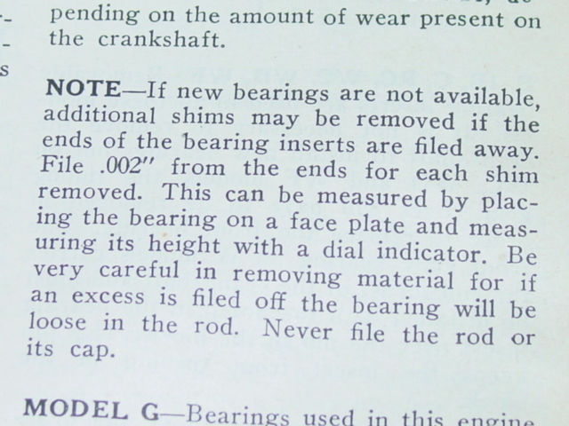
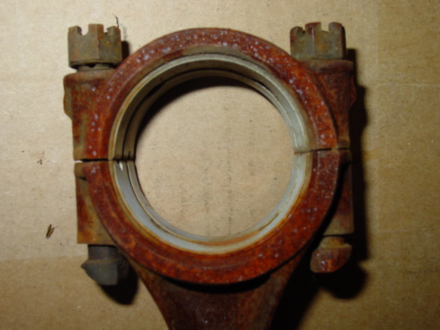
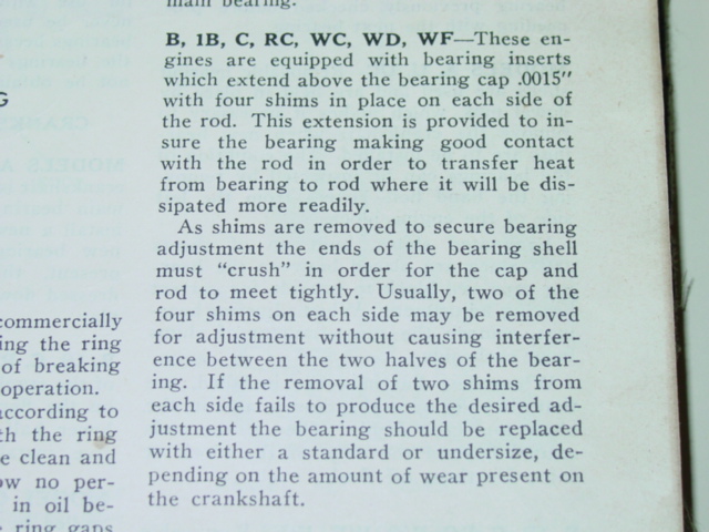
I don't have a scaner here at home to scam the page but here is a picture form a manual of the filing of the ends. New bearing inserts in (new) rods will have .0015 crush per insert. You have to only ask yourself when the shims are removed and they are not filed where does the material go. It can not enlarge the inside of the rod.
New bearing inserts on a slightly worn crankshaft will be the same as the below.

Picture046-vi.jpg
 
I you look at the gap between the rod and rod cap with the bearing inserts present and think about what happens to the inserts it you tighten the bolts enough to remove the gap.

AllisCRod-vi.jpg


I put this picture on in June of 2008 to help a person solve the same type of a problem.
It is by no means a new problem. It comes up quite often with people that have not worked on rod or main bearings that you remove shims to correct clearance problems. I had it happen to me on the first one that I removed shims on many years ago. I found my answer in the manual that I took the picture of and just posted above. That manual was printed in the 1940's
 

OK, I can see that, but it does say that you can remove 2 shims without taking any off the bearing shell ends..
Your crank is tight..need to check to see why..possibly add a shim on one or more bearings..

Would the crank turn rather easily with just the mains installed..?
If it did then there must be a tight Rod bearing..

Ron..
 
(Usually) Without causing interference. If the crankshaft is tight it has interference or it wouldn't be tight.
The caps should all be loosened up and one at a time tightened and checked for tightness and when tunning freely work on the next until all turn freely.

I love it. Keep questioning me and I will get all the bases covered.
At 73 I get a little lax on getting all the details in the first post.

A few of the tractor pix. You can click on (public home) for hundreds more pix
Picture Link
 
loosen the rod bolts all 1 turn so all are finger loose. That will give them an extra .002 -.004 clearance. Now try to roll the motor over. It that dont work, loose the mains one at a time till it rolls. Which ever bearing is tight, add .002 and torque, then roll and test. Roll and test after you tighten each bearing.. Plastic gauge sounds good, but the final test is to roll and see how it feels. If you honed and installed new rings they will have some drag. The crank should roll VERY easy by itself. AFter installing the pistons and rods i have noted it might take 20 ft pounds to roll the crank. I have checked that with a torque wrench.
 
plastic gauge assumes that the bearings are all line bored and the crank is perfectly straight. On an old motor, the alignment might be off .002 which would make the crank bind when tighening all the bolts. Be better if it was exact, but adding a shim to the dragging bearing will fix it.
 
Are you sure that your got the bearing caps and rods in the same position as the came out? Getting them mixed up can cause them to bind. #1 rod with # 1 cap on #1 journal 2/2/2 etc. Bob
 

Also double check the rods, I had one bent on a perkins engine and i didn't see it until it locked my engine down. I don't see as well as i used to.
 
I'm a bit confused, you're looking for a crank grinder AFTER you've purchased bearings? Your motor is apart, no mention of cam bearings. The motors I've had apart really needed cam bearings.

Did the main journals look good???? Seems to me your crank should have a high "ring" where the oil groove of the bearing doesn't wear the crank.

I just did a bottom end and used stones and sandpaper to grind the crank while it was in the block. I just used a 1/3 hp electric motor and belt to drive the crank from the front pulley with the block inverted on a wooden table. It took a few hours to fit and play with the shims until ALL the main caps could be torqued. I did all the rods on the crank while it was bolted to the flywheel OUTSIDE of the engine, just removing shims until free to move rods at proper torque.

A little perspective, this is a 125 cu in 20 HP slow revving motor not a formula 1 engine. I'd be willing to bet my junky rebuild will still be "just fine" a decade from now.

I'd also recommend a third hand when you install the rear main. I did mine alone and a bit of help would have been nice.

Good luck
 
Remember rods and mains are aligned bored and align honed. Caps must go on not only in same place, but same direction as well. Higher speed modern engines will break cranks if main caps are installed wrong. I require all my students mark rods and mains prior to disassembly. When going back together after final torque of any rod or main spin the crank that way you can determine which cap is involved if binding occurs. When done your rotating assembly should have no more torque than what Steve said, but will add that's rotating torque not breakaway torque. Hope this helps. Gerard
 
All of my rebuilds run strong and smooth. Which one are you referring to? I have been rebuilding engines since the 1950"s. Build and and raced stock a car in the 1960"s. I will see if I can get a video os some. I have the camera but have not worked on getting a video into the computer format. All I have done is on tape.

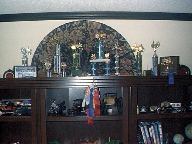
A small bit of success against others. I have never put them all in one place for a picture.

Photo0005-vi.jpg


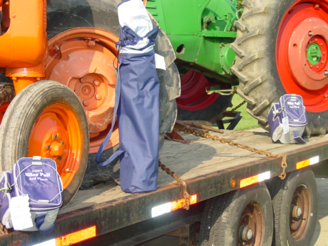
These were given instead of trophys. First with the C, second with the 77 and third with the B that was in the same class as the C.

RileyBenefitPullSept42004016-vi.jpg

Some Pull Pix
 

You had installed sbc valves...

Wondered if you used the original cam and how it did run..
I do valve-work, too...for myself and a select few..

Ron..
 
My C has a Crane ground cam for the 3 7/16 inch piston and 4 inch stroke of the engine. I have the stuff to cut the seats as well as the stuff to face valves in my home shop. I have a mold building shop within my plastic factory with Three mills, two lathes working. two more that could be. I can mill heads and deck blocks here.
All of that is rough work compared to mold building. CNC pictures down in my fotki picture site.
 

Just amazing, the HP hidden under a plain old Valve...!!!

Mine is Snap-on valve Grinder, Blue Point Seat grinder...
Going to have to up-date to New style Stones...can't get the old ones anymore....
Which do YOU prefer..??
B&D stones won't fit..

Ron..
 
Souix Valve grinder and seat grinder. I buy the Souix stones. I watch and buy a job lot of stones and such on ebay. I have picked up some lots with some used and several new stones all for what one new stone would list for. I have not checked lately because I have a large supply.
My cutter tools for installing valve seats are kwik-Way.
 

We sell tractor parts! We have the parts you need to repair your tractor - the right parts. Our low prices and years of research make us your best choice when you need parts. Shop Online Today.

Back
Top