WD45 12v Gen wiring diagram

Can anyone correctly connect the dots? I placed this in another post but I"m afraid nobody will read that far down and it will not be seen. If I shouldn"t post again please erase this.
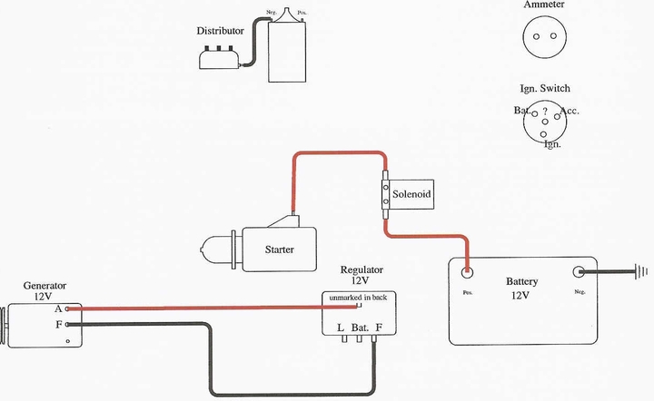
a5464.jpg
 
Capt. D,

I'll leave/post anything someone adds as long as it is correct. Just don't go by the pictures in my other post because they may not be correct I was posting the pics of my old setup so someone could help me.
 
your starter key might have another position. when you turn it clockwise it goes to the "run" position. does it go another to "start", that send voltage to the solenoid to crank the starter. when you let go of the key, it goes to "run" and you have voltage to the coil and regulator, not the starter.
you dont need the starter button if the key has the start position.

<a href="http://s436.photobucket.com/albums/qq86/steve-ill/?action=view¤t=a5464.jpg" target="_blank">
a5464.jpg" border="0" alt="starter wire
</a>
 
Steve, you made me a happy dude. You described my ignition switch exactly. I'll put everybody's input into getting it going tomorrow and hopefully get it wired and running again.

Thanks for showing exactly how the wires run.

Bob thanks for your time also.

Mark.
 
Yo Steve, you may wanna check that drawing. The VR's L terminal is always hot ya know so if the wire to the coil is on same switch terminal as shown, its always hot !!!!!!!!

When you have a 4 terminal, as opposed to only a 3 terminal VR, the L voltage feed up from the VR should go to the BAT input terminal on the switch instead of the switch getting its hot voltage feed (its BAT terminal) from the Load side of the ammeter as your sketch shows (When using a 3 terminal VR the switch then gets its voltage feed from the load side of ammeter).

Just remove that red wire from the ammeters Load side down to BAT on the switch and run the blue wire from L on the VR to BAT on the switch (instead of IGN as shown) and then shes correct. You sort of drew a 3 terminal VR diagram but mixed it with a 4 terminal VR.....

To wire a 3 terminal (BAT GEN FLD) VR its

BAT to load (NOT battery/starter) side of
ammeter
ARM/GEN to gennys ARM post
FLD to gennys FLD post
Lights and Ignition (their switch) get fed
voltage from the load side of ammeter via a
wire from it to the BAT input switch terminal

To wire a 4 terminal (BAT FLD L ARM/GEN) VR

BAT to load side of ammeter
ARM/GEN to gennsy ARM post
FLD to gennys FLD post
L (NOT ammeter) feeds hot battery voltage to
loads like lights or ignition via switch
lights and ignition

Hope this helps, God Bless yall

John T
 
John,

I don't know how I missed your reply I swear it wasn't there last night. I came in because she wouldn't start. Nothing happens at all. I'm going to try wiring it the way you just suggested.

Thanks.
 
Mark, what I told Steve corrects what in my opinion are errors on his drawing BUTTTTTTTTTTTTTTTTTTTT even as he had it shown if you depress a start button or turn a key type switch to the START position it should still have energized a starter solenpoid to make her crank. His way still had battery power to the BAT input terminal on the switch, I was just correcting where it got its voltage from (ammeter versus VR L terminal).

If it has a starter solenoid when you depress a push to start switch batetry voltage should get sent to the small S activation terminal (NOT any I terminal like on Ford type solenoids) on the solenoid making it pull in engage. Similar if its a key type when its in the START battery voltage gets sent to the small S activation solenoid terminal so it engages ANDDDDDDDD those switches need an input voltage on their BAT terminals.

If there with a test lamp this would be easy to diagnose but I cant explain everything over the net iof youre not already somewhat electrically experienced sorry

John T
 
John T,

Thanks for everything.

I realized one wire still had to be added from the center of the switch (st) to the ford solenoid (s post) and then I had painted and primered everything so I looked at the starter and sure enough when I had it off I got overspray inside on the commutator. A little sandpaper and she was good to go. She starts and shuts off and the ammeter shows a slight drop when I turn on the key but I'm not sure if I am actually charging while running....any suggestions on how to test to know for sure.

Thanks for everything. You helped me more than you know. I will post what I think is the correct diagram for my setup. Can you look one more time and see if everything looks good?

Thanks.

Mark.
a5557.jpg
 
Mark, yep thanks first to Steve and then my minor corrections and your new drawing THAT WIRING DIAGRAM IS NOW CORRECT

Heres my Troubleshooting Procedure for non charging.......

http://www.ytmag.com/cgi-bin/viewit.cgi?bd=farmall&th=665110

John T
John Ts Troubleshooting
 

We sell tractor parts! We have the parts you need to repair your tractor - the right parts. Our low prices and years of research make us your best choice when you need parts. Shop Online Today.

Back
Top