
Upgrading an Oliver Super 55 Electrical System My old Oliver Super 55 has been just sitting and rusting for several years now. I really hate to see a good tractor being treated that way, but not being able to start it without a 30 minute point filing ritual every time contributed to its demise. If it would just start when I turn the key, then I would use it more often. In addition to a bad case of old age, most of the tractor's original electrical system was simply too unreliable to keep. The main focus of this page is to show how I upgraded my Super 55's electrical system to a modern, more reliable one. There are three main electrical subsystems on the Super 55. These are the Starter circuit, the Generator circuit, and the Ignition System. There are other things such as fender lights and gauge lights, but I won't be getting into those here. One of the main things that I wanted to do was to convert the tractor from the old fashioned 6 volt, positive ground system to a 12 volt negative ground system. Virtually every kind of automotive electrical device built these days is made for a negative ground electrical system.
Now you recall that I just said that I wanted to convert from a positive ground to a negative ground system. With some electric motors, and starters are electric motors, they will spin backwards if you connect the electricity to them backwards. If a starter motor started spinning backwards, it's bendix gear would not be able to engage the flywheel because of the way that it is designed. Even if it did, the engine could not possibly start running backwards. Fortunately, the reverse running trait is only associated with permanent magnet motors. These are the kind of electric motors that have strong magnets instead of a field winding. While starter motors that have permanent magnet fields can run backwards, all starter motors that use a field winding will always run in the correct direction regardless of electrical polarity. While you will see permanent magnet starter motors every now and then, I can say with certainty that there were none ever installed on an Oliver Super 55. Therefore, there is no need to be concerned about the starter rotation when switching the ground polarity. So now that I have connected the 12 volt battery up to the 6 volt starter backward, will it burn the motor out? The answer is no. If we were talking about light bulbs (If your tractor still has them you should pay attention here) putting 12 volts to a 6 volt bulb would, to say the least, shorten its life tremendously. However, starter motors are different. They only run for brief periods of time. Applying double the voltage for the short duration that it takes to start an engine will not harm a starter motor. Well the starter part of the conversion was pretty easy. I hope you didn't work up too much of a sweat. However, since you are thinking starter right now, this might be a good time to mention that replacement brush assemblies for Oliver starters are still being made because they also fit some cars starters as well. If you are having any trouble with your starter, a new pair of brushes might be just the ticket.
While the starter will work correctly for either positive or negative ground systems, the generator is not so simple. The old Oliver generator was designed for a positive, not negative, ground system. Coupled with the fact that it was designed to charge a 6 volt battery and not a 12 volt battery, I decided that it was time to make the leap to an alternator system. Although the old 6 volt positive ground generators can be repolarized so that they work on a negative ground system, you still won't get enough voltage to charge a 12 volt battery. Even if you did, there is still the reliability factor. The first thing to do when replacing a generator with an alternator is to select a replacement alternator. I chose a GM 10 SI alternator because it is cheap and has a built-in electronic regulator. It comes in a variety of amperages, but if you get one, I suggest you ask your automotive store for an alternator matching part number 7127. Sometimes different manufacturers will add an extra digit or a letter, but "7127" will usually be in there somewhere. If the kid behind the parts counter can't handle that, just tell him you need one for a 1978 Chevy truck. At first you might be tempted to visit a junkyard for the alternator, but considering a remanfactured one typically retails for around $35, it really isn't worth it. The New Alternator Bracket The most difficult part of installing an alternator on the Super 55 is making a bracket with which to attach it to the proper place. While it is possible to attach the alternator with only a shoulder bolt and a handful of washers, using a solid bracket is the best method and is discussed in detail here. The old generator was mounted with bolts at both ends plus the belt tensioning bolt - three bolts total. The 10 SI is made to use only one long bolt plus the tensioner. This means that the rear bracket won't be used when installing the alternator. The front bracket is a different story. If you want the alternator mounted in a solid way, it will be necessary to fabricate a suitable replacement bracket as the old one will not work. If you aren't familiar with using a grinder and drill, it is a good idea to practice on a few test pieces before going all the way. It also helps if you have friends that already know how to fabricate metal brackets.
Once you have made the bracket, simply bolt it on where the old bracket was. The bottom of the alternator attaches to the bracket with a long 3/8" bolt and about a dozen spacer washers as shown in this photo. Make sure that the alternator pulley lines up with the crankshaft pulley. You can use the same tensioner bolt and tensioner bracket on top that the old generator used. Lastly, install the belt (preferably a new one) and tighten it with the alternator tensioner bolt. The mechanical portion of the alternator installation is now complete. Wiring the New Alternator
The alternator conversion and installation is now complete. Unlike the starter,
which didn't really require anything, the alternator conversion does take
a little bit of effort.
As I stated at the beginning of this page, the main reason for allowing the old Oliver to sit and rust was because of having to file the points every time I wanted to start it. The points will oxidize and fail if the engine isn't run periodically. Consequently, I didn't try very often. This made things even worse. What I needed was an electronic ignition module to replace the old points. I was quite surprised to find that there was so much support for Oliver tractors on the Internet - particularly at the Yesterday's Tractors web page. I found a few Electronic Ignition module companies, but they required that the distributor be permanently altered (by cutting) in order to make it fit. I was opposed to this because I wanted to be able to put everything back the way it was in the event that it didn't work as promised. Also, I would advise everyone reading this to steer clear of "point amplifiers". These are boxes that mount on the outside of the distributor and allegedly preserve the points by reducing the current that flows through them. Essentially, they are electronic ignition units that use the points themselves as the pickup mechanism. They are worthless as far as tractors are concerned. If you purchase an Electronic Ignition unit, make sure that it uses a magnetic pickup device. Finally, I found a good one. Before I bought it, I told the technician that I didn't want to start the installation process if it was going to require any welding, sawing, or special tools. He assured me that I could complete the installation with nothing more than a screwdriver and a pair of pliers. I bought one, and he was right. Their modules look essentially like a big aluminum washer with a plastic blob on it with wires sticking out of it that gets installed inside the distributor in place of the points and condenser. It seemed kind of small, but after installing it, the tractor started right away - even after sitting for 3 years. In fact, I photographed the entire installation process so that others can see how easy it is.
Now I have installed the electronic ignition module "washer" using the same
screw that used to hold the points in place. I also put the screw that held
the condenser back in even though it really doesn't hold anything. Around
the center shaft is a molded plastic magnetic inducer. This piece of plastic
actually has four magnets in it that are precisely aligned to fit my distributor
in this new configuration. The form fitting plastic makes it difficult to
install incorrectly. Note that you have to feed the two wires through the
hole where the insulator post used to be and install a rubber strain relief
grommet.
Your tractor's new electronic parts can be harmed if you connect the battery the old positive ground way!
The fixing up process is far from over, but at least now I have something that will start when I crank it and recharge the battery while running. The new alternator electronic ignition unit greatly increase the reliability of the tractor to the point where it can be used more often. Just letting it sit is probably the worst thing that you can do to a tractor. Hopefully, those days are over.
We sell tractor parts! We have the parts you need to repair your tractor - the right parts. Our low prices and years of research make us your best choice when you need parts. Shop Online Today. Copyright © 1997-2024 Yesterday's Tractor Co. All Rights Reserved. Reproduction of any part of this website, including design and content, without written permission is strictly prohibited. Trade Marks and Trade Names contained and used in this Website are those of others, and are used in this Website in a descriptive sense to refer to the products of others. Use of this Web site constitutes acceptance of our User Agreement and Privacy Policy TRADEMARK DISCLAIMER: Tradenames and Trademarks referred to within Yesterday's Tractor Co. products and within the Yesterday's Tractor Co. websites are the property of their respective trademark holders. None of these trademark holders are affiliated with Yesterday's Tractor Co., our products, or our website nor are we sponsored by them. John Deere and its logos are the registered trademarks of the John Deere Corporation. Agco, Agco Allis, White, Massey Ferguson and their logos are the registered trademarks of AGCO Corporation. Case, Case-IH, Farmall, International Harvester, New Holland and their logos are registered trademarks of CNH Global N.V.
Yesterday's Tractors - Antique Tractor Headquarters |
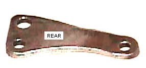 To
make the new bracket, you need to find a large enough piece of stock metal
about 1/4 to 3/8 inch thick. Next, trace the footprint of the old front bracket
onto it including the two mounting holes. Draw an additional 3/8" hole about
an inch over the upper hole by extending the height of the bracket drawing.
This extra hole will be used to mount the alternator. Now drill the smaller
holes making sure that you get them in the same position as the original
bracket. Then drill the larger 3/8" hole. Using a grinder with a cutoff wheel,
shape the stock metal to match the pattern you have drawn. Make sure that
each hole has at least 1/4" of metal around all sides - anything less will
be too unstable. This photo shows what your new bracket should look
like.
To
make the new bracket, you need to find a large enough piece of stock metal
about 1/4 to 3/8 inch thick. Next, trace the footprint of the old front bracket
onto it including the two mounting holes. Draw an additional 3/8" hole about
an inch over the upper hole by extending the height of the bracket drawing.
This extra hole will be used to mount the alternator. Now drill the smaller
holes making sure that you get them in the same position as the original
bracket. Then drill the larger 3/8" hole. Using a grinder with a cutoff wheel,
shape the stock metal to match the pattern you have drawn. Make sure that
each hole has at least 1/4" of metal around all sides - anything less will
be too unstable. This photo shows what your new bracket should look
like.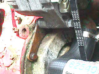 To finish the
bracket, you will need to weld a 3/8" nut to the rear of the 3/8" hole. To
do this, get a long, scrap 3/8" bolt and thread a scrap nut onto it about
an inch down from the end. Put the end of the bolt through the front of the
bracket and screw on the nut that you will be welding to the rear of the
bracket. When this is tight, you can use the bolt to hold the piece and weld
it easily. You should not attempt to weld a nut without having a bolt threaded
through it. If you do, the nut will warp and you won't be able to get the
mounting bolt through it. In fact, don't remove the bolt until the bracket
has cooled. When welding, it is important not to use too much heat or else
you might weld the scrap bolt and nut together!
To finish the
bracket, you will need to weld a 3/8" nut to the rear of the 3/8" hole. To
do this, get a long, scrap 3/8" bolt and thread a scrap nut onto it about
an inch down from the end. Put the end of the bolt through the front of the
bracket and screw on the nut that you will be welding to the rear of the
bracket. When this is tight, you can use the bolt to hold the piece and weld
it easily. You should not attempt to weld a nut without having a bolt threaded
through it. If you do, the nut will warp and you won't be able to get the
mounting bolt through it. In fact, don't remove the bolt until the bracket
has cooled. When welding, it is important not to use too much heat or else
you might weld the scrap bolt and nut together!
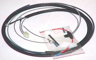 The
old generator wiring cannot be used for the alternator. The best thing to
do is remove and replace it with a new one. These can be purchased
for about $20.
They come with all the necessary connectors, wires, and diodes. With my tractor,
I also went the extra mile and purchased a new pair of heavy duty battery
cables, and a dash gauge set from a local automotive store. The gauge set
was kind of expensive at $50, but it included new gauges for oil pressure,
amps, and water temperature. With those installed, the new wiring harness
attaches to the ampmeter and the ignition switch. The exact wiring instructions
are included with the new wiring harness.
The
old generator wiring cannot be used for the alternator. The best thing to
do is remove and replace it with a new one. These can be purchased
for about $20.
They come with all the necessary connectors, wires, and diodes. With my tractor,
I also went the extra mile and purchased a new pair of heavy duty battery
cables, and a dash gauge set from a local automotive store. The gauge set
was kind of expensive at $50, but it included new gauges for oil pressure,
amps, and water temperature. With those installed, the new wiring harness
attaches to the ampmeter and the ignition switch. The exact wiring instructions
are included with the new wiring harness.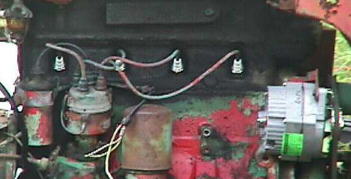 Here
is a photo of the tractor's electrical parts before the installation of the
electronic ignition unit has begun. The tractor has been in the family since
the early 1970's. Before that, it belonged to someone who liked little red
tractors. The tractor looks a little strange now that half of the cheap red
paint has flaked off to reveal the Oliver green underneath. On the right
of the photo, you can see the alternator that I have also begun to install.
At the time that this photo was taken, I was in the middle of the alternator
installation procedure.
Here
is a photo of the tractor's electrical parts before the installation of the
electronic ignition unit has begun. The tractor has been in the family since
the early 1970's. Before that, it belonged to someone who liked little red
tractors. The tractor looks a little strange now that half of the cheap red
paint has flaked off to reveal the Oliver green underneath. On the right
of the photo, you can see the alternator that I have also begun to install.
At the time that this photo was taken, I was in the middle of the alternator
installation procedure. 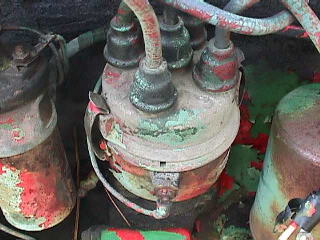 In
this photo, you can see a close-up of the original distributor cap and coil.
Although not shown in this photo, I have already replaced the spark plugs
with new ones prior to beginning the installation process. The old ones were
badly corroded from moisture and non-use.
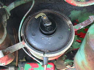
In
this photo, you can see a close-up of the original distributor cap and coil.
Although not shown in this photo, I have already replaced the spark plugs
with new ones prior to beginning the installation process. The old ones were
badly corroded from moisture and non-use.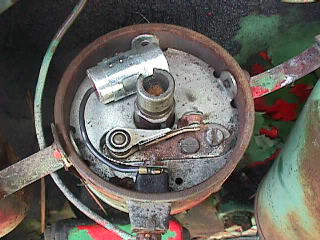 The
installation process begins by removing the distributor cap and dust plate
to reveal the original points and condenser.
The
installation process begins by removing the distributor cap and dust plate
to reveal the original points and condenser.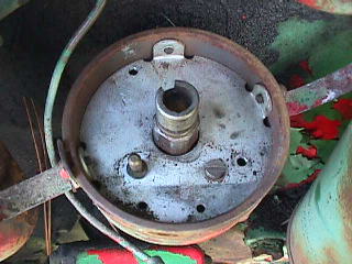 In order to install the electronic ignition kit, you have to
remove the old points and condenser and the plastic insulator post that connect
them. With a screwdriver, I removed the points and condenser in the usual
way. I had to use the pliers to get the post out. The important thing to
remember is that the original equipment has not been damaged and could be
reinstalled if necessary.
In order to install the electronic ignition kit, you have to
remove the old points and condenser and the plastic insulator post that connect
them. With a screwdriver, I removed the points and condenser in the usual
way. I had to use the pliers to get the post out. The important thing to
remember is that the original equipment has not been damaged and could be
reinstalled if necessary.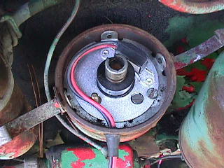
 Once the electronic ignition module was installed in the distributor, it
was just a simple matter of reinstalling the new cap, rotor and dust plate.
The hard part was over.
Once the electronic ignition module was installed in the distributor, it
was just a simple matter of reinstalling the new cap, rotor and dust plate.
The hard part was over.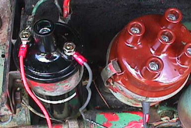 In this photo,
I have replaced the old 6 volt coil with a brand new 12 volt coil that has
an internal resistor. The connections are pretty simple. The red wire goes
to the positive side of the coil. The black one goes to the negative side.
The positive side of the coil also goes to the ignition switch. The old coil
was for a positive ground and had the negative side going to the ignition
switch, but since everything is negative ground now, we have to do it this
way.
In this photo,
I have replaced the old 6 volt coil with a brand new 12 volt coil that has
an internal resistor. The connections are pretty simple. The red wire goes
to the positive side of the coil. The black one goes to the negative side.
The positive side of the coil also goes to the ignition switch. The old coil
was for a positive ground and had the negative side going to the ignition
switch, but since everything is negative ground now, we have to do it this
way.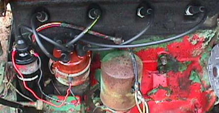 Lastly, I have installed a new set of spark plug wires. When
I cranked the tractor for the first time after installation, it started right
up. It spit a bunch of rust out of the exhaust pipe which I assume was from
sitting for so long.
Lastly, I have installed a new set of spark plug wires. When
I cranked the tractor for the first time after installation, it started right
up. It spit a bunch of rust out of the exhaust pipe which I assume was from
sitting for so long.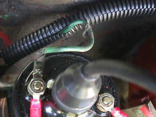 One thing about the wiring harness is that there is room to slide
the old ignition wire in there. There is a slit that runs the length of the
harness. This photo shows how I slipped the old coil wire in with the alternator
wires. This is totally unnecessary, but it gives the tractor wiring a cleaner
look.
One thing about the wiring harness is that there is room to slide
the old ignition wire in there. There is a slit that runs the length of the
harness. This photo shows how I slipped the old coil wire in with the alternator
wires. This is totally unnecessary, but it gives the tractor wiring a cleaner
look.