Third Brush GeneratorsWhile I love straightening sheet metal, cleaning, and painting old tractors, I use every excuse to avoid working on the electrics. I find the whole process sheer mystery. I have picked up and attempted to read every auto and farm electrics book with no improvement in the situation. They all seem to start with a chapter entitled "Theory of Electricity". After a few paragraphs I usually close the book and go back to banging out dents. A good friend and I were recently discussing our tractor electrical systems when he stated "I figure it all comes back to applying Ohms Law". At this point I deftly changed the subject with something like "Do you realize how important it is to bang the dents out from the furthest point of damage" (you can use this as a subject changer with anyone interested in restoration). It worked. If you ignore the theory and look at the "mechanics of the electrics", it is a bit simpler to deal with. Here is my attempt to describe the normal 3rd brush generator system used on many older farm tractors and avoid all the magic of unseen stuff moving at the speed of light. My experience includes mid-century ACs, Farmalls, and Case's but others are similar. One disclaimer is that older tractors may have all manner of field modifications performed on them over the years which will cause some or all of this not to apply. Another is that though I have tried to make this discussion mechanical, one cannot get around mentioning:
The 3rd brush generator system is similar in concept to later generators and alternators in its purpose, which is:
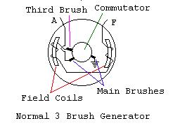
The generator has an armature that spins inside, brushes that contact against a surface at the back of the armature called a commutator, and coils that bolt up to the outside cases (these are the field coils). These items, combined with rotation, create an electrical and magnetic miracle to produce voltage (the "miracle" is sufficient for me, hopefully it works for you).
The more common generator has 2 terminals protruding from the case that you connect wires to. In a perfect world, there would be letters (A for armature & F for field) on the generator case that match perfectly to the schematic in your manual to allow you to connect all the correctly color-coded wires. That was in a perfect world. In the real world the letters are always long gone and manuals, from some manufacturers, expect that you already know which terminal connects to which wire. To top it off, the colors of the wires on your 50 year old tractor are no longer what the manual states they should be anyway (if the wires still exist). Before hooking up the system you will have to identify the type of system, which terminal is which, and which wire is which. You will also be identifying the method your generator uses to regulate output. On many tractors, it is what we can call a resistance light switch, others will have a voltage regulator of some sort and a few will have a simple preset fixed output device either in the generator or in the regulator.
Identifying the Generator TerminalsMost of the identification can be done by looking at the brushes (this unfortunately means some disassembly on many generators but some have an inspection cover that is easily removed). The 3rd brush generator gets its name from having an additional brush beyond the two main brushes found on later generators (4 for heavy duty and aircraft generators that need larger miracles).
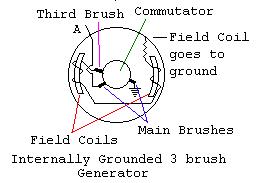
If you did not find 3 brushes, you have a 2 brush generator and this paper does not apply. If there is only a single terminal protruding from the generator case, your generator is internally grounded meaning the field coils attach to ground inside the generator. In this case, your terminal should be marked A and is the generators output terminal (skip the following paragraph and see below). The 3rd brush connects to the field coil and from there a terminal on the case. This terminal is the one connecting to the light switch or a resistance switch inside the regulator. Your manual may call this terminal F. The F Terminal tells the generator to produce more or less output. Do a continuity check to make sure the 3rd brush is not grounded when the F terminal is disconnected (this does not apply to internally grounded generators without F terminals). If it shows ground when disconnected, your field coil circuit is bad. The next brush should lead directly to a terminal on the case. Your manual may call this Terminal A. The output of the generator comes from this terminal. Do a continuity check for ground. If it is grounded, find out where hopefully the wiring is shorted and if not shorted, you may have a bad armature. The final brush should go directly to ground within the case. If you do a continuity check on this it might save you some later teardown woes. It should show a ground. Be sure to mark the terminals before reassembly. Using letter punches, make an A and an F at appropriate spots. Rebuild companies will sometime put stickers next to the unmarked terminals that have a nasty habit of falling off.
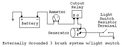
Identifying the WiresThe Output CircuitNow you know which the terminals are which. This won't do much good unless you can tell which wires are which. The first one to find is the one that actually charges the battery. It will lead to your battery from the ammeter, cutout relay, and A terminal on the generator (in that order, see schematics at the end of this discussion). If you remove the wire from the discharge or minus side of the ammeter you should be able to use your continuity tester (on your inexpensive Radio Shack voltage ohmmeter) to determine which of the wires is the other end. When you have decided which it is, this connects to the Battery side of the cutout relay (should have a B or Bat on it). The other terminal of the cutout relay (may be marked with G or Gen) connects to the A terminal on the generator. We have now figured out half the circuit.
The Output Controlling CircuitIf your tractor does not have a resistor light switch but instead has an F terminal on the voltage regulator, run a new wire from the F generator terminal to the F terminal on the voltage regulator and you're done. If it does have the resistor light switch, there should be a wire in the harness that runs from the light switch up to the generator. You can do a continuity test to ground to find it but unfortunately, cheap Voltage ohmmeters (VOMs) cannot tell you subtle levels of resistance. Your VOM cant tell if this wire is actually grounded (as it would be if the light switch were on), shorted to ground elsewhere or going to ground through the resistor. Since this could be a bad wire in your wiring harness, disconnect the leads from your light switch and trace the wire with the continuity tester (if it still shows a ground when unhooked, replace the wiring). This wire will connect to the generator terminal we marked with an F. While you can find the F wire easily this way, it does miss an opportunity to test the resistance of your light switch and possibly whether your generator will sufficiently charge when the lights are off. This has yet to bother me enough to justify the expense of a good VOM (my brother is one of those people that understands the "Theory of Electronics" and has often suggested that I purchase a quality VOM.. I have successfully resisted this on the basis that my tools should not cost more than my tractors).
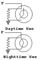
Output Control DevicesThe following devices are what tell the generator to not increase or reduce it's output. The only functional difference is that some can provide a high and low charge depending on conditions while others simply provide a fixed charging level. Output of the generator is determined by the position of the 3rd brush. These control devices are not designed to alter that setting, rather they merely actuate the output. The Resistor Light SwitchThe purpose of your light switch is reduce or increase the "amount of ground" (or resistance to ground) of the 3rd brush when the lights are on or when the operator knows that full charge is needed. The resistance it provides will determine the output of the generator. When the light switch is on or in high charge position, the third brush is grounded and the charge will be at its maximum. When it is off (or in low charge position), it still is grounded but in a "limited" fashion by the presence of a resistor. Some switches provide multiple levels of resistance. If the resistance is wrong the system will not work correctly. An open in the resistor will keep the generator from charging the battery. Likewise resistance from rusty, dirty, and broken-wire connections will alter the charging level. It is important that a clean connection from ground to the 3rd brush be provided to achieve high charge. Here is where the expensive VOM is useful to measure the resistance of the switch and wiring? Of course another option is to replace the switch and wires if charging problems are observed and the generator and cutout are known to be good. One other note on the resistor light switch. It is a dual function switch, one being the control of the 3rd brush and the other providing 6 volts to the lights. It is important that these functions are not confused for obvious reasons but if the wrong leads get connected or the switch is internally shorted, the system will be completely dysfunctional and will hopefully blow the fuse. Check your manual and test the light circuit side of the switch. If the hot side (that is supposed to run to the lights) shows that it is grounded, the switch is likely bad. Here is an schematic of the field resistor circuit of a simple resistor light switch.
The concept is the same on a Farmall Cub and letter series but there are more options. The big rotary resistor light switch has low charge, high charge, dim, and bright (some models have additional features such as rear lights thrown in).
The Voltage RegulatorOn some tractors, the light switch field control was not used. These would have a voltage regulator. It is commonly housed in the same box as the cutout relay and is either a single resistor or is another relay and a resistor. When the voltage regulator is used, the F terminal of the generator connects to the F terminal on the voltage regulator instead of a resistor light switch. The resistor-only regulator performs exactly as the light switch did when the lights were off. That is to say, it provides a resistance to ground and tells the generator to provide a fixed output. A use of such regulators would be tractors or power units sold with lights but no battery or starting system. In such uses, the generator would need to provide only a consistent level of current to light the lamp and would not have varying load conditions. The other type actually has another relay and a resistor in the case with the cutout. This relay bypasses the resistor until the generator output builds to a preset level. This level opens the contacts and once again lets the resistor slow the output. The normal regulator will repeat this cycle from 150 to 250 times per second. Another type, called a step-voltage regulator, does not cycle quickly, but holds the ground closed during load periods and places resistance back in the circuit when the load is reduced. For our purposes there is little difference. They both use the F terminal to control the 3rd brush, provide varied charge levels for load conditions, and have two relays in the regulator.
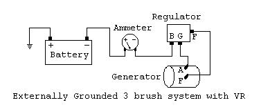
A Real Regulator and a Resistor Light Switch?If you have an externally grounded field coil and a resistor light switch, but your regulator has two relays and an F terminal, the regulator has likely been installed to eliminate your light switch as the method of increasing generator output. This may indicate that the switch was found to be faulty in the tractors previous life and they simply updated the system to a more modern voltage regulator. In the 50s this type of system began to be delivered as standard on many tractors but more often with the 2 brush system. Internal RegulationIf you did not have an F terminal, there is still regulation going on in the generator. The most interesting type uses a thermostatically controlled set of points in parallel to a resistor. These are connected to ground to approximate the function of external regulation. The thermostat heats up by running at a high charge causing the points to open which slows generator output. When it cools down the points close (once again connecting the 3rd brush directly to ground) and generator output increases until it heats up again. Another internal regulation method is to place the resistor in the generator case between the field coil and ground to provide steady fixed output. These systems simply provide output at preset levels that are enough to charge without overcharging. The Cutout RelayThe last part of the system is the cutout relay. This is a very simple magnetic switch with a single relay. The purpose of the cutout relay is to sever the connection to the battery at times that the generator output is low (like when your engine idles) and keep the battery from discharging back through the generator circuit. The relay's points close when the voltage is sufficient to complete the circuit to the battery. This simple relay is the basic system found on tractors that use resistor light switches or internal regulation. Other voltage regulators also have the cutout relay but it is housed with one or more additional relays (that is why the voltage regulator cases are larger).
Summary
A few things to remember:
|