King Kutter and 861 issue

Hi!

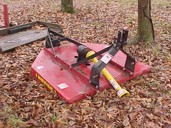
Could you all take a look at the attached pics and let me know your thoughts?

Problem--it seems the "Flex Hitch" on our King Kutter 5' rotary is too "high" for the 861. I cannot seem to adjust the height of the mower with the lift arms as the lever is almost all the way up. Any more movement on the touch control lever raises the mower all the way up. Also see the lift arms on the 861, they are quite high when the mower is 2" off the ground.

There seems to be plenty of "flex" in the Flex Hitch once the mower hits the ground, I can stop the lift arms and adjust them multiple points on the way down. But by then the mower is on the ground.

One thought I had was to move the pins for the lower arms down as far as I can by removing and drilling new holes. The problem is the design of the hitch will not let me move them much farther down without getting in to the "v" area where it is too tight.

Basically I think I need to have the whole hitch lower to better work with the 861. I saw some old J-Ds recently that had 3points and because they were so much taller than the 861, this "Flex Hitch" would probably work better for them.

Thoughts?

Thanks!
Chris

18468.jpg
18469.jpg
18470.jpg
18471.jpg
[/img]
 
might try this
ky redneck solution

the bottom bolt that goes through the hitch frame. the one that goes through the front eyelet of the short flexible hitch connector.


get two longer bolts and try attaching your two lower arms to that bolt on each side.

this would be just a trial temporary connection, but see if the tractor would pick up the machine higher and give you better level control.

if so, then you must figure out how to make this connection point a Permanent connection point for the two lower arms.

I do not know if you can see it in the attached picture, but to make my old Howse cutter work properly on my TO-35 ferguson, I had to add about a 4-5" extention (higher) connection point) to the top connector of the cutter 3 pt hitch frame. this gave the cutter more rear lift as for some reason my tractor 3pt hitch would just not lift the rear of the machine high enough.
with out hitting the pto shaft on front edge of the cutter.

I also have to take off my straight bar hitch, I see yours is still on the tractor, when I use the cutter.
it will hit the pto shaft.

they make these cutters to fit most all tractors.
but our little ford/fergy's, the pto shaft is much lower on the tractor, than it is on other makes
AC, farmall, oliver, john deere, etc.

hope this helps some,
main thing, be careful and safe. you do not want to get hurt or tear up your new cutter.
a119152.jpg
 
I've never seen such hitch. One wonders the purpose.

Nevertheless, I see nothing in the pictures that should prevent proper adjustment of mowing height using the tractors position control so long as the lift if properly functioning and adjusted.

Dean
 
In your pictures, the lift links (arms you say) are never much more than horizontal. They should reach maximum lift well above horizontal.
 
In your pictures, the lift links (arms you say) are never much more than horizontal. They should reach maximum lift well above horizontal.
 
In your third pic the position control lever is in the draft position, leastwise that is draft position on my jubilee. The position location (lever pointing up) will give much more control with the lift control lever to the right of the seat. Another important factor is the top link adjustment so that the PTO shaft doesn"t bind on the front edge of the mower deck when fully raised. Good luck. Dan Robertson
 
(quoted from post at 05:50:13 06/19/13) In your pictures, the lift links (arms you say) are never much more than horizontal. They should reach maximum lift well above horizontal.

Yes, that is where they are at when the mower is 2" off the ground. If I move the touch control lever any more up (you can see in one pic it is nearly all the way up) the arms will go full up and lift the mower all the way up.

That is the problem, I seem to be at the top of my "variable lift" when the mower is 2" off the ground. Any more movement of the touch control lever raises the mower 3 feet.
 
(quoted from post at 08:52:10 06/19/13) In your third pic the position control lever is in the draft position, leastwise that is draft position on my jubilee. The position location (lever pointing up) will give much more control with the lift control lever to the right of the seat. Another important factor is the top link adjustment so that the PTO shaft doesn"t bind on the front edge of the mower deck when fully raised. Good luck. Dan Robertson

Nope, on the 861, the lever horizontal is implement control.
 
(quoted from post at 01:21:31 06/19/13) might try this
ky redneck solution

the bottom bolt that goes through the hitch frame. the one that goes through the front eyelet of the short flexible hitch connector.


get two longer bolts and try attaching your two lower arms to that bolt on each side.

this would be just a trial temporary connection, but see if the tractor would pick up the machine higher and give you better level control.

if so, then you must figure out how to make this connection point a Permanent connection point for the two lower arms.

I do not know if you can see it in the attached picture, but to make my old Howse cutter work properly on my TO-35 ferguson, I had to add about a 4-5" extention (higher) connection point) to the top connector of the cutter 3 pt hitch frame. this gave the cutter more rear lift as for some reason my tractor 3pt hitch would just not lift the rear of the machine high enough.
with out hitting the pto shaft on front edge of the cutter.

I also have to take off my straight bar hitch, I see yours is still on the tractor, when I use the cutter.
it will hit the pto shaft.

they make these cutters to fit most all tractors.
but our little ford/fergy's, the pto shaft is much lower on the tractor, than it is on other makes
AC, farmall, oliver, john deere, etc.

hope this helps some,
main thing, be careful and safe. you do not want to get hurt or tear up your new cutter.

Good thoughts, will have to get some bolts to test.
 
(quoted from post at 09:01:18 06/19/13)
(quoted from post at 05:50:13 06/19/13) In your pictures, the lift links (arms you say) are never much more than horizontal. They should reach maximum lift well above horizontal.

Yes, that is where they are at when the mower is 2" off the ground. If I move the touch control lever any more up (you can see in one pic it is nearly all the way up) the arms will go full up and lift the mower all the way up.

That is the problem, I seem to be at the top of my "variable lift" when the mower is 2" off the ground. Any more movement of the touch control lever raises the mower 3 feet.
n that case, I suspect that your 3 point position control is not working properly. Adjustments and or cam & cam follower pin wear.
 
In that case, I suspect that your 3 point position control is not working properly. Adjustments and or cam & cam follower pin wear.


So are you saying that at the level the arms are currently at and the position of the touch control (pic below) I should still be able to control the position of the arms without them going full up?
 
(quoted from post at 10:59:18 06/19/13)
In that case, I suspect that your 3 point position control is not working properly. Adjustments and or cam & cam follower pin wear.


So are you saying that at the level the arms are currently at and the position of the touch control (pic below) I should still be able to control the position of the arms without them going full up?

18472.jpg
should still be able to control the position of the arms without them going full up?" Should have proportional position control over the full lift travel range.
 
(quoted from post at 11:03:09 06/19/13)
(quoted from post at 10:59:18 06/19/13)
In that case, I suspect that your 3 point position control is not working properly. Adjustments and or cam & cam follower pin wear.


So are you saying that at the level the arms are currently at and the position of the touch control (pic below) I should still be able to control the position of the arms without them going full up?

18472.jpg
should still be able to control the position of the arms without them going full up?" Should have proportional position control over the full lift travel range.

Gotcha...making sense now. Do you know the part number of the pin? I have the CNH "My Shed" app, but cannot seem to identify that pin.

How hard of job is it to replace the pin and remove the cam to be re welded? What gaskets do I need?

Thanks!
Chris
 
Replacing the pin is a straight forward affair once the lift cover has been removed. For proper results, you will also need a copy of the I & T FO-20 manual for the adjustment procedures.

Removing the ram arm and rewelding the cam, if needed, can be another matter if the upper lift arms and/or ram arm are badly siezed to the rock shaft.

Dean
 
Since ram arm is generally hard to remove, if it requires welding/grinding, I would do it in place & just clean up well afterward. Pin is 374072S. Top cover gasket is NCA502A. O-ring is 87033S94 & I don't know if you need one or two of them.
 
(quoted from post at 12:21:46 06/19/13) Replacing the pin is a straight forward affair once the lift cover has been removed. For proper results, you will also need a copy of the I & T FO-20 manual for the adjustment procedures.

Removing the ram arm and rewelding the cam, if needed, can be another matter if the upper lift arms and/or ram arm are badly siezed to the rock shaft.

Dean

Thanks Dean. Don't have the I&T manual, but have a Ford reprint. That manual should work?
 
Not unless you have the needed NuDay tools (or substitutes), which are required for the Ford adjustment procedures.

The FO-20 manual has "alternative" (special tools not needed) procedures.

Dean
 
Said another way, is the pin that "could" need replacement #68 in the diagram from the I&T manual? Where is the cam that it rides on?

Thanks everyone for staying with me on this...
Chris

mvphoto18480.jpg
 
No.

It's 66.

The pictured pin is the one that you will break when adjusting the linkage if you do not use two wrenches when doing so.

Dean
 
Got it...

It rides against #80 the main pivot that the cylinder pushes on to turn the shaft to raise/lower. Now I see why it is a bear if it has to be welded on. Let's just hope that only the pin is worn...


I didn't realize the cylinder was part of the top cover. Should one renew the o-ring and backup ring on the cylinder while in there or don't those go bad.

Currently if you have a load on the arms, they slowly leak down in about 2 hours with the engine off. With the engine on, you can feel it "bump" the arms up slightly every 30 seconds or so. Barely any measureable lift, but you can feel it if you have a hand on the mower or lift arms. Does that mean cylinder issue or other items...
 
(quoted from post at 10:59:18 06/19/13) So are you saying that at the level the arms are currently at and the position of the touch control (pic below) I should still be able to control the position of the arms without them going full up?

What we're saying is that with the position control in it's current position, the arms should not be where they are at. They should be very close to all the way up, and they look to be only about halfway up. That is an indication that either the control linkage is out of adjustment or the cam follower pin is worn, or more likely both of the above.
 

Awesome! Thanks! I got the pin on order and will hope the cam doesn't need welding.

This is the answer I was looking for all along. I don't have a recent reference point as to how the arms should be in relation to the touch control.

Thanks!
CB
 
Get yourself the I&T manual if you don't already have it, as that has an "alternate" adjustment method that doesn't require the special Nuday tool that the Ford Shop manual says to use. The I&T manual lists both methods, but the Ford manual only has the method that requires the Nuday tool.
 
(quoted from post at 15:05:05 06/20/13) Get yourself the I&T manual if you don't already have it, as that has an "alternate" adjustment method that doesn't require the special Nuday tool that the Ford Shop manual says to use. The I&T manual lists both methods, but the Ford manual only has the method that requires the Nuday tool.

Roger that...I got the I&T manual yesterday. I only had the Ford manual before. Looks like it would be nice to have the Nuday tools... Have you done it without? Results?

Thanks to everyone for all the help on this topic, I appreciate it!
 
Just to put some reference to this post, should it get searched in the future...

I took the advice of posters here (and Soundguy) and got the pin and lift cover overhaul kit. Side note, I did get the cover gasket, lift cylinder seals (oring and leather) and pump tube orings from CNH. The gasket from CNH is more of a "rubberized" material versus the paper on in the TISCO overhaul kit. The leather backup ring from CNH is also "nicer".

Anywho, I pulled the cover off last week and pulled it all apart. Soundguy checked out a picture of the cam and declared it "good", but the pin was 50% worn through.

Renewed the pin and put it all back together. Needed just a touch of adjustment following the procedure in the I&T manual. Put it all back on the tractor. I took the cover off by myself, but had my Dad help me put it back on. Made some short "pins" to screw in to the center section to hold the gasket in place and give a guide to the lift cover. Used 3 grade 2 bolts, and lopped the heads off. The stuck up from the center section about 1.5" and the rear one had a slot cut in it to back it out with a screwdriver once the lift cover was in place.

Everything functions great!

Below are pictures of the arms in relation to the touch control with the new pin and adjusted. Have total control over the arms their entire range. Amazing how that worn pin can affect the resolution of the touch control so much.

Just wanted to close out this post in case anyone does a search and also to say thanks to everyone for helping!
Chris

mvphoto19996.jpg


mvphoto19997.jpg
 

We sell tractor parts! We have the parts you need to repair your tractor - the right parts. Our low prices and years of research make us your best choice when you need parts. Shop Online Today.

Back
Top