Wiring a 641 Ford - Accessory Question

RTR

Well-known Member
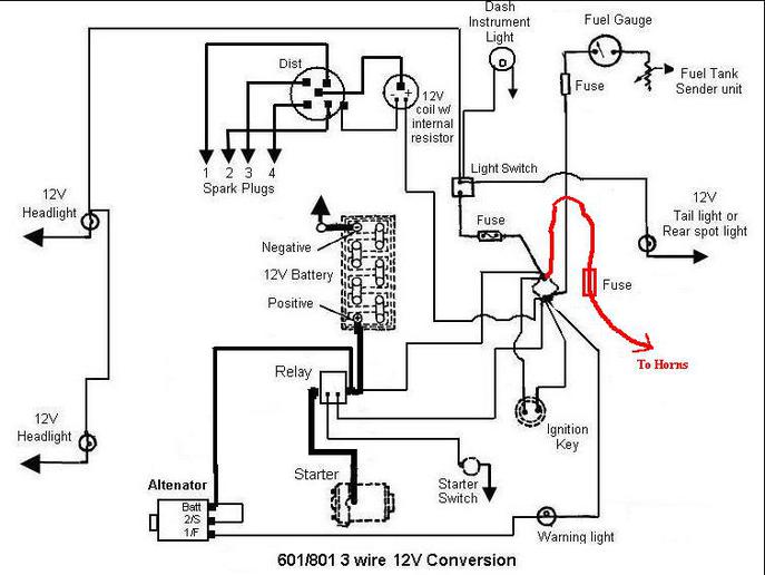
I am adding some 12 volt electric "air horns" to my 'reconditioned/restored' Ford 641 tractor. I have a question about how I should hook up the wiring regarding the diagram below. I feel like I should use an inline fused wire, and hook it to the junction block as per my drawing on the diagram.

Please provide me with input, thoughts, and concerns. THANKS!
a81069.jpg
 
You're good to go as long as you hook it to the Battery side of the junction block. The weak key switch would probably not be able to handle the current requirements for electric horns.
 
First, you probably know this and just forgot to mention it or put it in your diagram, you'll want to add some kind of switch (spring loaded push button or something similar) or the horns will be on all of the time with that diagram. Second, if you want to keep kids from wearing down your battery by playing with the horns when you're not around, you could install a relay that's controlled by a switch that's run off of the key switch, then the secondary side of the relay would connect the battery side of the terminal block to the horns via a fused line.
 
You are correct. I have a push button installed on the dash. Therefore, I guess the wiring diagram would read "To Horn Switch" instead of "To Horn".

Now that that has been said.....do I have the diagram drawn correctly?
a81072.jpg
 
Yes, the diagram is correct for a basic circuit to run the horn, but as I said, the horn will operate with the key switch in the off position, so there is a potential for someone, like kids, to run the horn when the key is off and for the battery to be run down as a result. If you have no worries in that regard, then it is fine as is.
 
(quoted from post at 13:20:54 09/01/12) I am adding some 12 volt electric "air horns" to my 'reconditioned/restored' Ford 641 tractor. I have a question about how I should hook up the wiring regarding the diagram below. I feel like I should use an inline fused wire, and hook it to the junction block as per my drawing on the diagram.

Please provide me with input, thoughts, and concerns. THANKS!
a81069.jpg

sure, it will work,
however, on big amp draw items like horns, a relay is a good idea.
simple horn-relay diagram here: (needs fuses/fusible links added)
http://www.secondchancegarage.com/public/133.cfm
 

Well if you have the time (and know exactly how it should go), take my wiring diagram and draw in what I need to complete the wiring for the horn USING A RELAY & FUSE SYSTEM.

I have a good idea of how it should go, but would like one of you experts to draw it out so I know I am right!

THanks again.
 
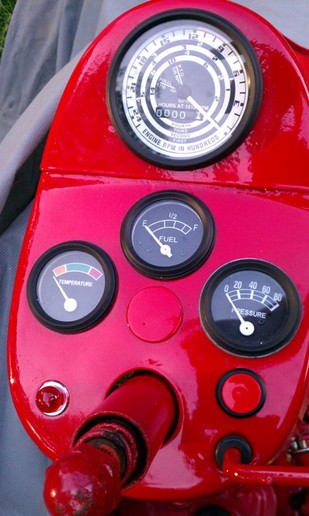
Well, those are not the original type of gauges for that tractor, so we don't know how the lights in them are supposed to work exactly, except for the basic electrical concepts of the lights in the gauges need to be connected to 12 volts on one side and good ground on the other to light up.

Was there any kinfd of instructions or schematic diagrams that came with the new gauges? If so ,posting them woulg give us a better idea of what you have.

I know you said in the video that you don't have a test light available, but you appear to have plenty of wire available, Have you tried connecting a wire from the hot side of the battery directly to one of the gauges while the other side of the gauge is connected directly to the negative terminal of the battery to see if it will light up? That will bypass all of the other wiring, and the light switch and concentrate on testing exactly how the gauges need to be connected for the lights to work.

Once you've got that figured out, then you can move your test wire from the hot side of the battery to the hot side of the light switch to see that you've got power to the switch, and then move it to the switched side of the switch to see if you get power there when you turn the switch on.
 
I did try hooking up a hot wire directly from the light terminal to the battery hot and got a spark


(quoted from post at 18:39:44 11/13/12) Well, those are not the original type of gauges for that tractor, so we don't know how the lights in them are supposed to work exactly, except for the basic electrical concepts of the lights in the gauges need to be connected to 12 volts on one side and good ground on the other to light up.

Was there any kinfd of instructions or schematic diagrams that came with the new gauges? If so ,posting them woulg give us a better idea of what you have.

I know you said in the video that you don't have a test light available, but you appear to have plenty of wire available, Have you tried connecting a wire from the hot side of the battery directly to one of the gauges while the other side of the gauge is connected directly to the negative terminal of the battery to see if it will light up? That will bypass all of the other wiring, and the light switch and concentrate on testing exactly how the gauges need to be connected for the lights to work.

Once you've got that figured out, then you can move your test wire from the hot side of the battery to the hot side of the light switch to see that you've got power to the switch, and then move it to the switched side of the switch to see if you get power there when you turn the switch on.
 

We sell tractor parts! We have the parts you need to repair your tractor - the right parts. Our low prices and years of research make us your best choice when you need parts. Shop Online Today.

Back
Top