Generator and regulator type A or B match ???

Crazy Horse

Well-known Member
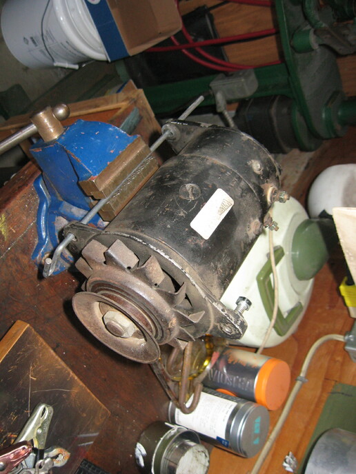
I have a 6 volt generator here, photo below. I think it's a Delco (someone might verify that) but there is no ID on it, the manufacturer's tag is gone but there is a rebuilder's tag on it with some meaningless numbers but it does say 6V. It was on a '45 Massey Harris 101 junior but it is definitely NOT a 3rd brush generator (that would use a light switch charge control and one relay cutout like those had originally). This one came from maybe an auto application, I guess it doesn't matter.

When I had it on the tractor and all wired up (like when I got it) and the tractor running, it did not show a charge at the ammeter or at the battery terminals. I did a 'motoring' bench test yesterday and the generator does motor, the pulley turns in a clockwise direction viewing from the pulley end (see the photo), the same direction the pulley would turn when rotated by the tractor's V-belt when running.

The generator has two internal brushes at the far end and has the expected field (F) and armature (A) terminals. It has a 3-tab regulator (with three coil towers inside). One is tagged B (the generator cutout relay circuit) and it hooks up to the ammeter. The other two are marked F (to field F on the generator) and G (to armature A on the generator). Those would be for voltage and current control from what I read, I'm not sure which tower controls the volts or amps.

So first question ...... does the motoring test indicate (or maybe even guarantee) that the generator 'should be' working when hooked up and driven by the engine?

Second question ....... I have read where there are two types of 3-tab regulators, type A and type B. This is where I become clueless, I suspect maybe that the wrong type of regulator might be on it, or maybe it has the correct regulator but it just isn't working properly. The regulator has 6V painted on the cover by someone.

Any suggestions for me without getting too complicated? Like do I have the correct voltage regulator (even if it might not be working correctly)? Or how do I tell type A from type B without going back to school and which one should match up to this generator?
cvphoto121963.jpg
 
Thanks Greg, I'm flying blind with this reply to you (because I don't understand how a generator really works) but I did some simple continuity tests (which I I generally understand). With reference to the last section of your link you provided (A or B circuit ??) .....

First, each of the two brushes (inside the far end of the generator) individually show continuity to ground (the generator case). This is not involving the F or A terminals on the generator, just a test from the brush wire itself to the case. Then, the two brushes show continuity between them as well in a separate check. I am assuming that one of those brushes should be insulated from the case, is that correct?

The field terminal on the generator has a wire leaving it inside and it goes to one of the big coils that surround the armature. That generator field terminal tests continuity to ground (the generator case) and also to both brushes in separate tests.

The armature terminal on the generator is wired directly to one of the two brushes. That armature terminal tests continuity to ground (the generator case) and also to both brushes (just like the field terminal did).

Something doesn't sound right to me if your link is saying that one of the two brushes should not ground to the case (or is not insulated).
 
That sounds WRONG... my b gens use a positive voltage from the regulator to the field terminal, to make/gnerate voltage. The field leads are NOT grounded at the field terminal! The other end of the field coil is ground internally, but not the field terminal. What am I missing here?


Where an A gen, the internal: end of the field coil is tied to positive, and you use a varying ground from the regulator..at the field terminal to generate.
 
Ground the field terminal to test for full output on an A system. The regulator controls the grounding of the field coils. So, the field terminal should not have continuity to the generator housing.

"Feed the field" (apply power to the field terminal) of a B system to test for full output. The regulator controls the power feed to the field coils. So, there should be continuity between the field terminal and the generator housing.
 
Maybe I can help here because I went through this a few times and it finally stuck. Someone please correct me if it's wrong.

In an A circuit the field is internally energized by having one end connected to the ungrounded brush with the other end to the F terminal. The ungrounded brush connects to the A terminal. The output is controlled by grounding the F terminal through the regulator.

In a B circuit the field is internally grounded (to the grounded brush or the case) with the other end connected to the F terminal and energized from the regulator.

So, in an A regulator the F tab is a path to ground. In a B it's a path from the battery.

Polarizing requires different methods but I've never had to do a B so I can't splain that.
Hope this helps.
 
Here's a simple test.

With the engine running and up to speed (not idling), the regulator wire disconnected, check the F terminal with a test light or voltmeter to ground.

If you get a voltage reading, it is a type A. Ground the F terminal, it should full charge.

If there is no voltage, it is a type B. Jump from the non grounded side of the battery, it should full charge.

It won't hurt to experiment, get it wrong it just does nothing. Just don't experiment with the regulator connected.

As for determining the regulator, you can take the cover off and trace the circuitry, see where the path of the F circuit goes.

If it goes to ground, its an A, if it goes to the battery, it's a B.

Usually the problem with a regulator is the field contacts are worn or dirty, may just need filing. The contacts are held closed by a spring, so at rest there should be continuity through the contacts.
 
Thanks Steve .... I copied your reply below in parts and have put in some QUESTIONS IN CAPITALS.

With the engine running and up to speed (not idling), the regulator wire disconnected, check the F terminal with a test light or voltmeter to ground. If you get a voltage reading, it is a type A. Ground the F terminal, it should full charge.

QUESTIONS: 1)SO EVERYTHING IS WIRED UP AS USUAL FOR THIS TEST EXCEPT FOR ONE REGULATOR WIRE? WHICH REGULATOR WIRE IS DISCONNECTED? OR ARE MORE THAN ONE REGULATOR WIRES DISCONNECTED? 2)SO 'FULL CHARGE' WOULD BE SEEN AT THE AMMETER WHEN THE F TERMINAL IS GROUNDED?

If there is no voltage, it is a type B. Jump from the non grounded side of the battery, it should full charge.

QUESTIONS: 3)JUMP FROM THE NON-GROUNDED SIDE OF THE BATTERY TO WHERE? TO THE FIELD TERMINAL ON THE GENERATOR? AND FULL CHARGE IS SEEN AT THE AMMETER?

It won't hurt to experiment, get it wrong it just does nothing. Just don't experiment with the regulator connected.

QUESTIONS 4) SOUNDS LIKE ALL WIRES TO THE REGULATOR SHOULD BE DISCONNECTED FOR THIS TEST, LIKE TOTALLY REMOVED?

As for determining the regulator, you can take the cover off and trace the circuitry, see where the path of the F circuit goes. If it goes to ground, its an A, if it goes to the battery, it's a B.

QUESTIONS 5) SO DISCONNECT THE REGULATOR COMPLETELY FROM THE TRACTOR TO DO THIS TEST? SO THESE ARE CONTINUITY TESTS BETWEEN THE REGULATOR'S F TERMINAL AND GROUND (THE REGULATOR BASE)FOR TYPE A .... OR BETWEEN THE REGULATOR'S F TERMINAL AND THE REGULATOR'S BATTERY TERMINAL IF TYPE B?
 
Not absolutely 100% positive, but I have never seen the Stepped barrel Delco, as pictured, that was not a 12v, A-circuit. All the continuity measurements you did are correct, i.e., A to F, A to gnd, f to gnd......all will show continuity. Another correction is that in a B circuit, the field voltage source, being switched by the field contacts, is the Armature terminal, not the Batt terminal of the regulator. One more "quickie" is that in about 99% of the time if the 3 VR terminals (when facing your eyes) are ordered left to right, A-F-B, then it is B-circuit, and of B_A_F, the it is A-circuit.
 
QUESTIONS: 1)SO EVERYTHING IS WIRED UP AS USUAL FOR THIS TEST EXCEPT FOR ONE REGULATOR WIRE? WHICH REGULATOR WIRE IS DISCONNECTED?

The F Field wire.

QUESTIONS: 3)JUMP FROM THE NON-GROUNDED SIDE OF THE BATTERY TO WHERE? TO THE FIELD TERMINAL ON THE GENERATOR? AND FULL CHARGE IS SEEN AT THE AMMETER?

Yes. It may not peg the meter, but should charge at full capacity of the generator. Don't run it very long like that.

QUESTIONS 4) SOUNDS LIKE ALL WIRES TO THE REGULATOR SHOULD BE DISCONNECTED FOR THIS TEST, LIKE TOTALLY REMOVED?

No, only disconnect the field wire from the generator. Don't let it touch ground if it's a B.

QUESTIONS 5) SO DISCONNECT THE REGULATOR COMPLETELY FROM THE TRACTOR TO DO THIS TEST?

Yes, it needs to be out of circuit to prevent false readings. Probably be easier to get it off so you can see it better.

SO THESE ARE CONTINUITY TESTS BETWEEN THE REGULATOR'S F TERMINAL AND GROUND (THE REGULATOR BASE)FOR TYPE A .... OR BETWEEN THE REGULATOR'S F TERMINAL AND THE REGULATOR'S BATTERY TERMINAL IF TYPE B?

Yes, you should be able to manually open and close the various contacts with the ohm meter connected and determine if the contacts are making connections. There are resistors on the back to help stabilize the voltage. Take those in consideration. The main thing you will be looking for is the contacts making good low resistance connections.

Just like ignition points, they corrode and arc, sometimes needing filing. A points file is the proper tool, not sand paper! Be sure to get a very thin one so it will fit without altering the clearance settings.
 
Thanks JMor, good info. On a search I came across an old YT reply post of yours on polarizing A & B generators from 2014 I think it was. A very good explanation there with some diagrams that you sourced. My regulator shows the BAF tab sequence so likely an A-circuit I suspect.
 
(quoted from post at 09:06:50 04/04/22) Thanks JMor, good info. On a search I came across an old YT reply post of yours on polarizing A & B generators from 2014 I think it was. A very good explanation there with some diagrams that you sourced. My regulator shows the BAF tab sequence so likely an A-circuit I suspect.
hank you.
 

We sell tractor parts! We have the parts you need to repair your tractor - the right parts. Our low prices and years of research make us your best choice when you need parts. Shop Online Today.

Back
Top