Used red MN tachometer

Dingo3

Member
Location
Southern MD
I figured it out. Found another old tach I forgot about.
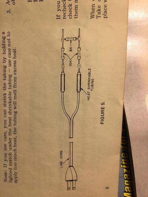
Came with instructions. Two 0.1 uf capacitors soldiered on the board and Im good. It also had this cool diagram to make a test lead so the calibration pot can be adjusted before you install it in the vehicle.
cvphoto119621.jpg
 
L have one of the Hallicrafter kit tachs that my father in law who was heavily into kit electronics assembled and gave to me for a Christmas present some years ago. I had it set up to use with a V-4 Johnson 60 hp outboard. When I sold the boat it got put back in the box and has been in there for 30+ years. The tach was very good and it had a very steady needle and it used the wire around the spark plug cable for a pickup. It really needs a new home because it is just sitting in the box on the shelf along with all the instructions and extra parts to change the calibration of it for 4,6 or 8 cylinder engines.
 
I get around 25 volts AC at 60 cycles across the test leads?? Assuming the tach is high impedance...With a possible current flow of 316 ma to 400 ma max at a lower impedance and lower voltage. Guessing the tach will probably be around 8k impedance,by the design. That would mean 14.1 volts at 176 ma current through the tach and the parallel resistor carrying the same? Been a few years.
 
Standard 120v AC is dropped down to 60 Hz voltage to the tach. The Cal Pot can then be adjusted for use with the different cylinders. 8 cyl. would be set at 800 rpm, 6 at 1050 and 4 at 1700. This is all above my pay grade but seems pretty easy to do. They had good instructions back then.
 
Edit: They dont say what the voltage is dropped to. Only a safe and usable voltage is stated. Your figures are probably correct.
 
Hey, Dingo 3, I stand corrected, the tach is a Heatkit tachometer and not a Hallicrafters, Hallicrafters made short wave radios and such. The tachometer is a Model MI 18-2 and can be configured for both 6,000 rpm and 9,000 rpm. It can be calibrated for two or 4 cycle engines. Send me an e-mail and I'll send you some pictures of it.Italso has the instruction book and all the stuff for calibrating it.
 
Gene, I sent you an email at about 9:00 am this morning. Hope I got the right address. Should be addressed from Austin. Thanks
 
Sorry, been away from the forums a couple days. The calculations and values given by soxbill probably would have made more sense to me right after I completed an introduction to electronics course in the late 90s. That was part of the curriculum for my studies for Nondestructive Evaluation. However, I did not use a lot of that knowledge so it was forgotten. My original posting about setting your tach up to operate by electronic pulses from a magnetic pickup on the crank pulley was just a sort of ..brain teaser.. for the electronic gurus on the forum. More so curious what type of circuitry was needed to complete such a task. Thanks for giving a reply with information on your findings.
 

We sell tractor parts! We have the parts you need to repair your tractor - the right parts. Our low prices and years of research make us your best choice when you need parts. Shop Online Today.

Back
Top