
Geo-TH,In
Well-known Member
There has been a lot of chatter about ballast resistors, burnt points and primary current so I decided to measure primary current and coil voltage.
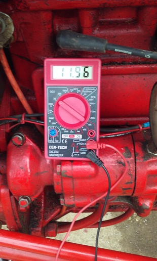
Keep in mind when I bought my Jubilee it had already been converted to 12v. My battery is a 2007. The battery voltage is a little weak, 11.96v, tractor RUNS JUST FINE and STARTS JUST FINE TOO.
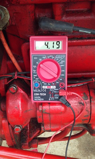
I found something very interesting. When the points are closed and I turn the key on, the coil voltage starts out at 6v. It steadily decreases to 4v in less than a minute. Battery voltage is holding at 11.96v.
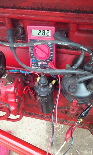
The primary current starts out at 4 amps, like JohnT and JMOR said it would. However the current steadily decreases to 2.82 amps as the coil voltage decreases. BTW, I'm still using the original points that came on the tractor. I've put over 250 hours on it. Again, the tractor runs just fine. Spark plugs are very clean, no carbon.
The decreasing voltage and current can only be explained one way. Before I post my theory as to why, I'll like the experts opinion on what's going on.
Now when tractor is running, the alternator is putting out a little over 14v, so coil will get slightly more volts and slightly more current. How would you measure the amps when tractor is running? There will only be primary current when points are closed and no current when points are open. So is my tractor operating with only 2.82 amps going to the coil when the points are closed?
In one of the pics, you may see a diode with the anode pointing at the coil. This is my way of by passing the ballast when I hit the start button. I'm taking the starter voltage, the cranking voltage, and applying it via the diode to the coil. Yes, I know the diode is using .6v, so not all the cranking voltage is applied to the coi. I get a hotter spark that way. By passing ballast is the old school way my 1965 barracuda was wired.
Keep in mind when I bought my Jubilee it had already been converted to 12v. My battery is a 2007. The battery voltage is a little weak, 11.96v, tractor RUNS JUST FINE and STARTS JUST FINE TOO.
I found something very interesting. When the points are closed and I turn the key on, the coil voltage starts out at 6v. It steadily decreases to 4v in less than a minute. Battery voltage is holding at 11.96v.
The primary current starts out at 4 amps, like JohnT and JMOR said it would. However the current steadily decreases to 2.82 amps as the coil voltage decreases. BTW, I'm still using the original points that came on the tractor. I've put over 250 hours on it. Again, the tractor runs just fine. Spark plugs are very clean, no carbon.
The decreasing voltage and current can only be explained one way. Before I post my theory as to why, I'll like the experts opinion on what's going on.
Now when tractor is running, the alternator is putting out a little over 14v, so coil will get slightly more volts and slightly more current. How would you measure the amps when tractor is running? There will only be primary current when points are closed and no current when points are open. So is my tractor operating with only 2.82 amps going to the coil when the points are closed?
In one of the pics, you may see a diode with the anode pointing at the coil. This is my way of by passing the ballast when I hit the start button. I'm taking the starter voltage, the cranking voltage, and applying it via the diode to the coil. Yes, I know the diode is using .6v, so not all the cranking voltage is applied to the coi. I get a hotter spark that way. By passing ballast is the old school way my 1965 barracuda was wired.

