Farmall 12 Volt issue

I have a Super M that has been converted using a delco three wire. The voltage at the battery was 16-17 volts while running. I thought I had a bad regulator inside the alt so I replaced with new alt. Same issue. I had alt tested and it is good but why am I getting 16 - 17 volts in the charging system? Battery is at 12.7 when everything is off. I will boil the battery putting that many volts into it.
 
(quoted from post at 22:47:12 12/01/11) I have a Super M that has been converted using a delco three wire. The voltage at the battery was 16-17 volts while running. I thought I had a bad regulator inside the alt so I replaced with new alt. Same issue. I had alt tested and it is good but why am I getting 16 - 17 volts in the charging system? Battery is at 12.7 when everything is off. I will boil the battery putting that many volts into it.
ssuming that you have an accurate meter, where do you have the Sense wire connected? Did you possibly reverse the connections to the 2 wire alternator connector?
 
The tractor was wired before I got it. From what I can tell. Main big wire to post is hot, there is a jumper from that main hot post to one terminal labeled 2, then there is a wire that comes off the ignition to oil pressure switch that gets 12 volts on other side and turns hot once oil pressure is sensed to the other terminal that says 1. So all three are hot once oil pressure is sensed.
 
There are only two possible reasons for excessive voltage. One , easiest to check and repair is the sense lead that goes to number two termial. If that connection is not good , meaning making a tight clean connection to the spade on the regulator, your voltage can be all over the place. I used to play with those connectors while running alternators on the test stand. I found that if I inserted a variable resistor (pot) in line from battery to number two I could get readings way up to 20 volts. Seems backwards as one would think a poor connection would lead to lower voltage but IH had sent out a bulletin warning of these conditions. Therefore, if that wire and connector are good, check the main wire all the way to battery. Other problem would be alternator itself. Some times the current draw through the field (rotor) seems to destroy a regulator. I have had about three alternators that I replaced regulators, rotors, diode bridge, diode trio (everything but the stators) and they still over charged. Different alt and problem solved. Also, there has been a rash of poor quality regulators in the parts systems.
 
(quoted from post at 23:03:56 12/01/11) The tractor was wired before I got it. From what I can tell. Main big wire to post is hot, there is a jumper from that main hot post to one terminal labeled 2, then there is a wire that comes off the ignition to oil pressure switch that gets 12 volts on other side and turns hot once oil pressure is sensed to the other terminal that says 1. So all three are hot once oil pressure is sensed.
iring sounds good. I would try another voltmeter for comparison.
If really trying to put 17v on battery, it ought to be pumping out many amperes..........don't have ammeter in circuit do you? If putting out lot of amps, pull the 2 wire connector & you will probably detect change in engine load with your ears.
 
It does have ammeter and it is pegged on charge side at full RPM, slight discharge when at idle.

I did take off both spade connector wires and the voltage dropped to around 14.5 to 15.3 but it sholdnt work at all with both spades off right?

Second alternator since first was same way bought new and it is same way.
 
check the wiring, it should match this diagram provided by Farmall Bob.
http://s101.photobucket.com/albums/m46/farmallbob/Farmall%20Tractor%20Wiring%20Diagrams/?action=view&current=05-12vAlternatorConv-rev4_22_08.gif
 
(quoted from post at 23:33:00 12/01/11) It does have ammeter and it is pegged on charge side at full RPM, slight discharge when at idle.

I did take off both spade connector wires and the voltage dropped to around 14.5 to 15.3 but it sholdnt work at all with both spades off right?

Second alternator since first was same way bought new and it is same way.

Once the alternator starts charging voltage from an outside source is no longer needed on the excite (No. 1) terminal for the alternator to continue to charge, in fact, it is providing internal voltage on that terminal. That is what turn the charge indicator light off on systems equipped with a light. Once the alternator stops charging it will again need excite voltage for it to start again.

Delco regulators should be equipped with a safeguard feature that shuts the alternator down if there is no voltage sensed on the number 2 terminal. With all the after market regulators available you can find some that shut the alternator down completely and some that will go to maximum charge. Others will maintain a preset voltage.
 
Sounds like your sense wire, (#2 on the rear alt case at the regulator plug) , is not connected to full battery voltage or the wire has a bad connection.
The #2 sense wire "senses system voltage and tells the alternator to charge hard enough to maintain about 14.5 volts. If a wrong or bad connection to the sense wire is sending the alternator a false low voltage signal, the alternator will increase the charge rate to compensate for this false signal..
Do you have the #2 sense wire connected directly to the big BAT stud on the alternator rear ? That is the best place, then it reads voltage right at the alternator.

A Delco SI series alt will continue charging even if the regulator plug is disconnected, because the regulator continues to recieve voltage from the internal diode trio, so yes, they will charge with the regulator plug disconnected if already excited(charging) when the plug is pulled.

The issue can be confused by the many different aftermarket regulators avalible for that alt.

The original Delco regulators of the 70's would default charge only about 1 volt above normal if the sense wire went open or the regulatpr plug was disconnected.
The problem is that some aftermarket regulators react differently to losing the sense connection, some will charge flat out 17+ volts, while others will quit charging if the sense wire is disconnected.
My first move would be to connect the #2 wire directly to the BAT stud on the alternator and see if the charging voltage returns to normal.
 
Make sure the #1 wire is connected before (between ign switch and resistor) any inline ignition resistor so It sees full 12V
 
FWIW I agree with the gents who think the voltage sensing circuit/lead isnt getting a good connection to the battery.

1) Try a jumper wire connecting the little No 2 terminal up to the big rear main output stud on the alternator n see what happens?????

2) Try a jumper wire connecting the little No 2 terminal on the alternator direct to the batteries Pos post n see what happens???

Take two aspirins n call me Monday at the office.

John T
 
OK John, i will try that. It already has a jumper from Bat term to 2 term and I am having the issue, I will make another one and see what happens and then try it straight to the pos battery terminal.
 
You might be on to something. See the number 1 wire was wired odd I think. It comes off one side of the oil pressure switch so when I turn on key there is no voltage to the number 1 post until oil pressure is sensed and it completed the circuit in the switch. this may take a few seconds and thus is my issue. I think the coil should be routed through that switch to shut off engine if oil pressure drops not the alternator. Maybe I should try a different hot wire to post 1 on alternator.
 
The small wire in the two wire plug on the alt has to much voltage feeding the alt. Add a 10 ohm 10 watt resistor from radio shack to the small wire in line somewhere..Problem solved..
 
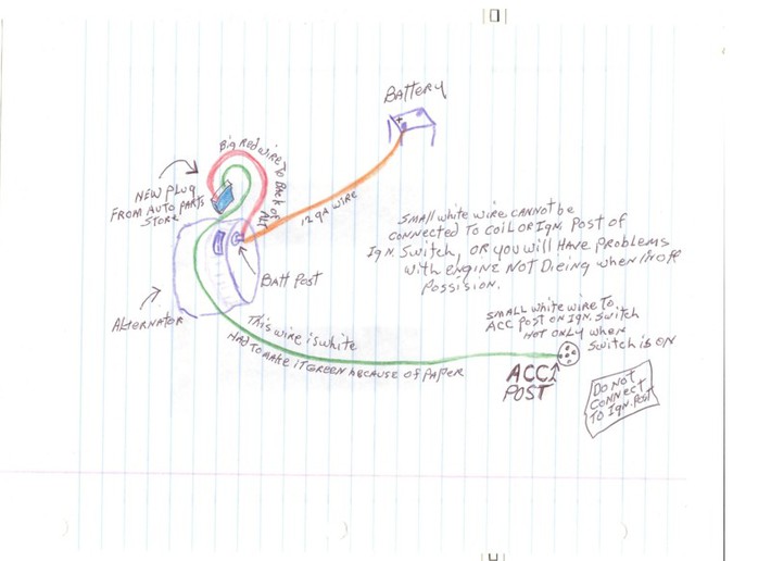
Here is a picture of how an alt should be wired. I wired my H Farmall this way years ago and never a problem since.. Course this is just my opinion..
I had to change the color of the white wire in the plug because of the white paper..
a55259.jpg

Untitled URL Link
 
Connecting the small wire in the alt plug to the battery or to the post on the rear of the alt will cause an over charge if the alt is in top notch shape. the small wire is the one that needs the 10 ohm 10 watt resistor inline and should be connected to the ign switch like in the drawing..
 
(quoted from post at 15:16:54 12/02/11) Connecting the small wire in the alt plug to the battery or to the post on the rear of the alt will cause an over charge if the alt is in top notch shape. the small wire is the one that needs the 10 ohm 10 watt resistor inline and should be connected to the ign switch like in the drawing..

The resistor on the No 1 terminal is used to prevent full charging amperage from coming through that wire if there was a failure of the main battery connection to the alternator. The No 1 terminal has charging voltage applied to it internally through the diode trio in the alternator. If there is a break in the wire connecting the battery to the alternator the total output of the alternator will be available at the No 1 terminal. With no resistor, light bulb, or diode in the circuit the 14/16 gauge wire and possibly the ignition switch could be overloaded and damaged. The excess currant through the diode trio can also ruin it. Incidentally, IH used a 25 ohm resistor on tractors with an ammeter gauge.


Excess voltage applied the the No 1 terminal should not cause the alternator to increase the charging voltage. Charging voltage is controlled by varying the resistance to ground of the rotor field coil. At any voltage above the maximum charging voltage of the regulator will cause the field circuit to open and stop all current flow. Residual magnetism in the rotor can still allow a minimum amount of charge but it will be very little. A field coil shorted to ground may cause the alternator to charge with no control by the regulator but would be rare. I have never seen that happen. Generally failures of the field coil are open circuits, not shorts to ground.
 
Ahhh I see. I am wired similiar. See the 2 prong plugs on alternator are labeled 1 and 2. 2 being the top one and 1 being the bottom. My jumper from cable post on alt goes to the top prong or number 2. My Number 1 goes to 12v ignition (they are opposite from your picture).

your picture has the plugs opposite than what mine is wired. And my main cable that goes to alt comes from ammeter not the battery.
 
Check the accuracy of your Meter. 12.7 volts is pretty hot for a battery not being charged. 12.6 if juswt pulled off of charging. Accurate readings are very important. Jim
 
Using an oil pressure switch to open the #1 excite circuit is a very good, goof proof way to excite the alternator, just make sure the power supply to the oil pressure switch is full battery voltage, not down stream of a resistor that may feed it a false low voltage signal or place a load on the #1 alt terminal.
Even with the OP switch, you should still add a diode or idiot light(may be hidden)in the #1 lead.
This will prevent a backfeed from the #1 alt terminal overloading and damaging the diode trio and regulator inside the alternator.
 
Scott, I hadn't notice that I drew that plug with the wires crossed, sorry about that.

Scott, When I do this I buy a new plug from the auto parts store, when I tell someone how I do this, I tell them to buy a new plug from the auto supply before they start. The new plug will have a 12 ga wire and a 14 ga wire(pigtails) and the plug will only plug into the alt one way so you can't go wrong. The 12 ga wire in the plug connects to the pos post on the back of the alt, the 14 ga wire in the plug is the one you add the 10 ohm 10 watt reistor to and it connects to the IGN switch as in the drawing..
 

We sell tractor parts! We have the parts you need to repair your tractor - the right parts. Our low prices and years of research make us your best choice when you need parts. Shop Online Today.

Back
Top